Optical pickup device

a pickup device and optical technology, applied in the field of optical pickup devices, can solve the problems of difficult access, difficult to reproduce all three types of discs using only a single objective lens, and may influence the signal characteristics, so as to improve the reproduction or recording performance, and the effect of stable servo signals

Inactive Publication Date: 2008-06-05
LG ELECTRONICS INC
View PDF3 Cites 4 Cited by
  • Summary
  • Abstract
  • Description
  • Claims
  • Application Information

AI Technical Summary

Benefits of technology

[0028]Accordingly, the present invention has been made keeping in mind the above problems occurring in the prior art, and an object of the present invention is to provide an optical pickup device, which reduces interlayer interference in a multi-layer disc, thus obtaining stable servo signals and improving reproduction or recording performance.

Problems solved by technology

In this case, there is a disadvantage in that signal characteristics may be influenced by the extent of adjustment.
However, since the numerical apertures of objective lenses required for the recording / reproduction of CD, DVD, and BD differ greatly from each other, it is almost impossible to reproduce all three types of discs using only a single objective lens.
When the objective lenses are arranged in the radial direction, it is not easy to access the innermost circumference of the disc, and thus an optical pickup in which two objective lenses are arranged in the track direction has been developed.
As shown in FIGS. 5A and 5B, there occurs a problem in that an SPP signal is excessively distorted due to noise light from another layer, and a DPP signal calculated based on the SPP signal, that is, a tracking error signal, is degraded.
That is, when a disc having two or more recording layers is reproduced or recorded, noise occurs in reproduced signals and servo signals due to the beam reflected from another layer, as shown in FIGS. 4 and 5, and thus reproduction or recording performance may be deteriorated by this noise, and recording may occasionally be impossible.

Method used


Image

  • Optical pickup device
  • Optical pickup device
  • Optical pickup device

Examples


Embodiment Construction

[0077]Hereinafter, embodiments of the present invention will be described in detail with reference to the attached drawings.

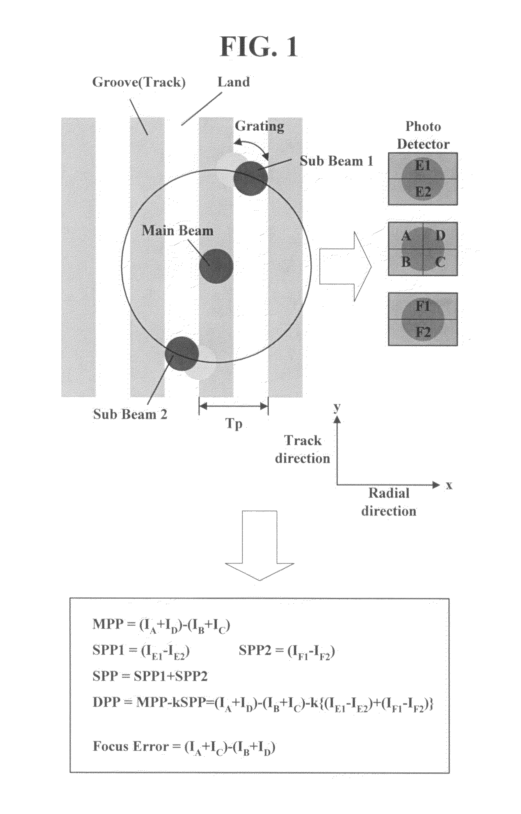
[0078]In a DPP method using 3 beams, sub beams are focused on a disc while being spaced apart from a main beam by a ½ track pitch. In a typical case where an objective lens is disposed on the central axis of a disc, the relative positions of the main beam and the sub beams are not changed regardless of the inner and outer circumferences of the disc.

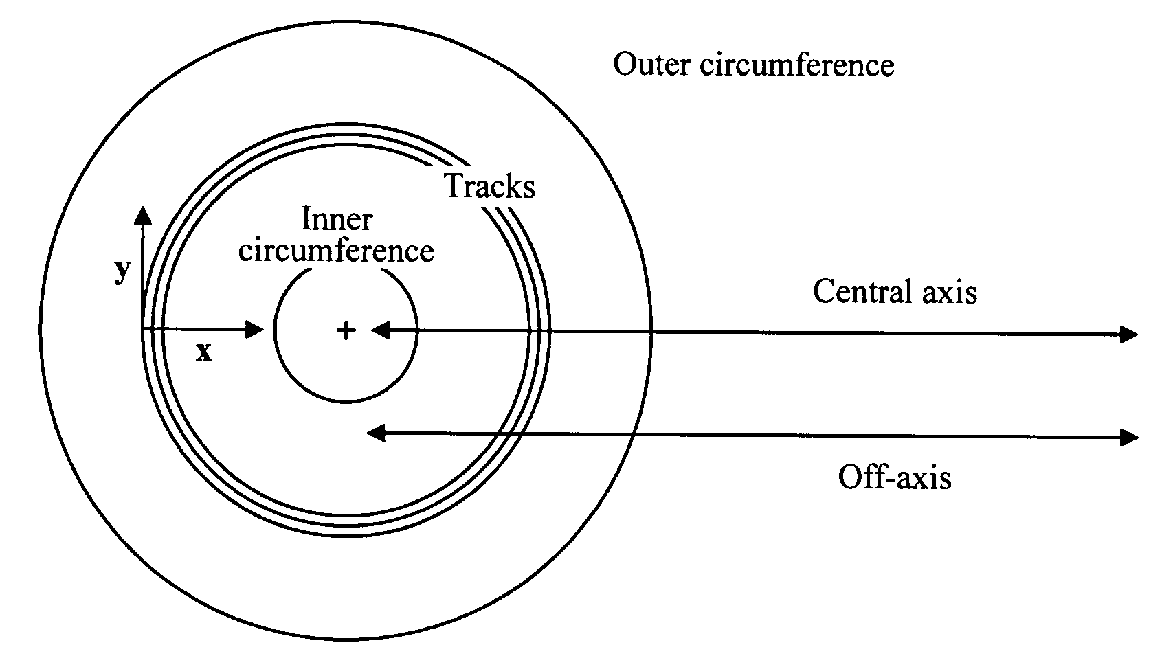
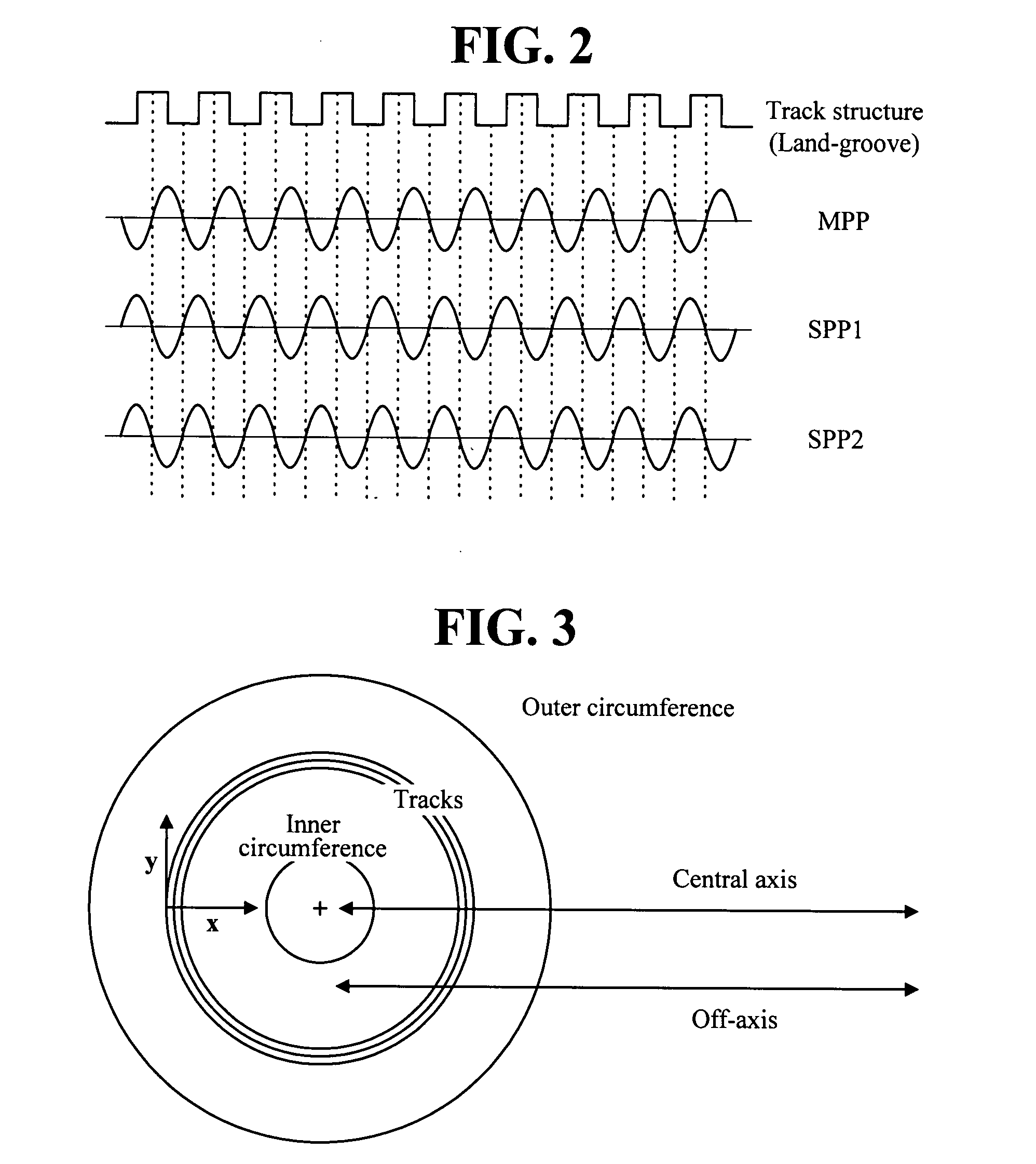
[0079]However, in the case of an off-axis arrangement, in which an objective lens is operated while deviating from the central axis of a disc, as shown in FIG. 3, the relative positions of the main beam and the sub beams on the track of the disc are changed according to the inner / outer circumference of the disc. In this case, there is a problem in that, as shown in FIG. 6, the offset of a DPP signal increases at the boundary of recording / non-recording areas of the disc, and the interval during which the offset occurs...


PUM

PropertyMeasurementUnit
distanceaaaaaaaaaa
distanceaaaaaaaaaa
wavelengthaaaaaaaaaa

Abstract

Disclosed herein is an optical pickup device. In an embodiment of the present invention, sub beams from which an AC component has been removed are generated using a first diffractive element based upon properties that a beam incident on a disc is reflected with being separated by the track structure of the disc, and beams reflected from adjacent layers are prevented from being diffracted to sub cells for receiving the sub beams using a second diffractive element. In this case, the grating direction of the first diffractive element and the second diffractive element is adjusted, and thus the influence of dead zones generated in a tracking error signal due to the second diffractive element is removed.

Description

PRIORITY STATEMENT[0001]This application claims the priority of Korean Patent Application Nos. 10-2006-0057235, filed on Jun. 26, 2006, Korean Patent No 10-2006-0061956 filed on Jul. 3, 2006 and Korean Patent No 10-2006-0079192 filed Aug. 22, 2006 in the Korean Intellectual Property Office, the disclosure of which is incorporated herein in its entirety by reference.BACKGROUND OF THE INVENTION[0002]1. Field of the Invention[0003]The present invention relates, in general, to an optical pickup device and, more particularly, to an optical pickup device, which can prevent noise, generated from other layers, from flowing into servo signals.[0004]2. Description of the Related Art[0005]Ever since a Compact Disc (CD), which is an optical storage medium capable of storing up to 74 minutes of audio (music) or 650 Mbytes of data has been marketed, a Digital Versatile Disc (DVD) capable of holding two hours of Standard Definition (SD)-level video has been widely commercialized. Further, a Blu-ra...

Claims


Application Information

Patent Timeline
Patent Type & Authority Applications(United States)
IPC IPC(8): G11B7/00G11B7/135
CPCG11B7/0903G11B7/1353G11B2007/0013G11B2007/0006G11B7/1378
Inventor YIM, BOO BIN
Owner LG ELECTRONICS INC
Why Eureka
Try Eureka