
Optical head and apparatus for optically recording and reproducing information

a technology of optical recording and information, applied in the direction of optical recording heads, data recording, instruments, etc., can solve the problems of complex detection optical system, large size, and ineffective use of laser beams to generate main light beams for recording, etc., to achieve the effect of large size and complicated detection optical system

Inactive Publication Date: 2008-08-21
HITACHI MEDIA ELECTORONICS CO LTD
View PDF17 Cites 20 Cited by
  • Summary
  • Abstract
  • Description
  • Claims
  • Application Information

AI Technical Summary

Benefits of technology

"The present invention provides an optical head and an optical information recording and reproducing device that can stably obtain a servo-signal when recording and playing information on a plurality of information recording faces. This is achieved by using a diffraction grating to effectively divide a laser beam into a main light beam for recording and two sub-spots on the disk, and by arranging an optical sensor for tracking at the outside of the stray light. The invention simplifies the detecting optical system and reduces the size of the optical sensor."

Problems solved by technology

Therefore, there is fear that a detecting optical system is complicated and has a large size.
In JP-A-2006-344380, a diffraction grating is arranged to divide a laser beam emitted by a laser beam source to be supplied to one main spot and two sub-spots on a disk, and whereby there is fear that the laser beam is not effectively used to generate a main light beam for recording.

Method used


Image

  • Optical head and apparatus for optically recording and reproducing information
  • Optical head and apparatus for optically recording and reproducing information
  • Optical head and apparatus for optically recording and reproducing information

Examples


first embodiment

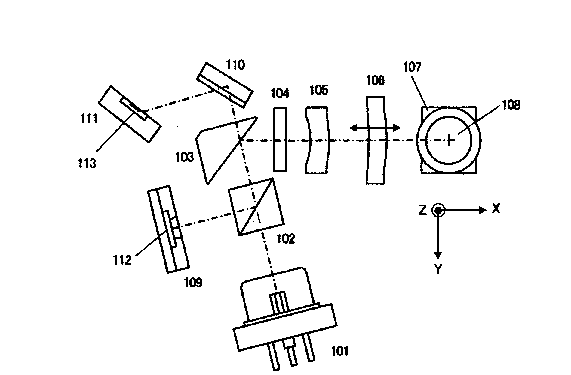
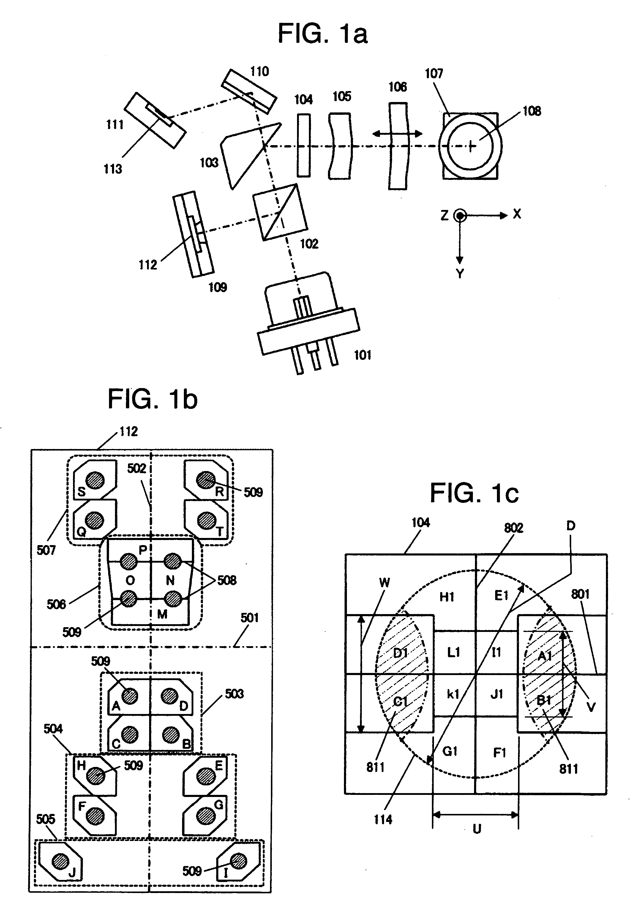
[0035]A first embodiment of the invention is described with making reference to FIGS. 1a-11b. Regarding this embodiment, a basic structure of an optical head for BD is described with making reference to FIGS. 1a-1c. Incidentally, the embodiment does not need to be used only for BD, and is applicable to, for example, an optical head for HD DVD, a compatible optical head for BD / DVD / CD, or the like.

[0036]FIG. 1a is an upper view showing schematically the optical head for BD. A light beam with band of 405 nm as a divergent linearly polarized light is emitted from a BD laser beam source 101, passes a polarizing beam splitter 102, a BD reflection mirror 103 and an optical beam multiple-dividing element 104 and a BD assistant lens 105, and is converted to a collimated light beam as a substantially-parallel light beam by a BD collimating lens 106. The BD collimating lens 106 is driven along an optical axis by a BD collimating lens driving mechanism (not shown) as shown by an arrow mark. Fur...

second embodiment

[0068]A second embodiment of the present invention will be explained using FIG. 12 to FIG. 15.

[0069]FIG. 12 is an upper view showing schematically an optical head for BD in this embodiment. The second embodiment differs from the first embodiment explained using FIG. 1 in that a focusing lens 1201 is arranged between a light exit surface 1202 of a polarized beam splitter 102 and a BD optical sensor 109. The other parts are the same as those in FIG. 1 and explanations thereof will be omitted here.

[0070]FIG. 13a shows the result of reducing a magnification of a return route which is an optical path from a BD data layer to the BD optical sensor 109 (synthetic focal distance of BD assistant lens 105, BD collimating lens 106 and focusing lens 1201÷focal distance of an objective lens 108) from about 12 times (=approach route magnification) to 10 times, 8 times that in the first embodiment and obtaining, through a diffraction optical calculation, an image of light beam diffracted by the gra...

third embodiment

[0073]A third embodiment of the present invention will be explained using FIGS. 16 to 18. FIG. 16 shows a light receiving surface pattern of a light receiving portion 112 of a BD optical sensor 109 in this embodiment. This embodiment differs from the first embodiment in FIG. 5 in that a third light receiving surface 1603 is formed by moving I away in the direction shown by an arrow mark 1602 and moving J away in the direction shown by an arrow mark 1601. Incidentally, I and J shown with dotted lines indicate the positions of the first embodiment in FIG. 5. Since the other parts are the same as those in FIG. 5, explanations thereof will be omitted here.

[0074]FIG. 17 shows a BD information recording medium having two data layers of an L0 layer (cover layer having a thickness of about 100 μm) and an L1 layer (cover layer having a thickness of about 75 μm) and an example of calculating, when light is focused on the target L0 layer, a distribution of unnecessary light reflected from the ...


PUM

PropertyMeasurementUnit
focal distanceaaaaaaaaaa
diameteraaaaaaaaaa
diameteraaaaaaaaaa

Abstract

An optical sensor has first light receiving surfaces having respective pentagonal or hexagonal shapes and being independent of each other, and second light receiving surfaces having respective hexagonal shapes and being independent of each other, third light receiving surfaces having respective hexagonal shapes and being independent of each other, fourth light receiving surfaces having respective hexagonal shapes and being independent of each other, and fifth light receiving surfaces having respective hexagonal shapes and being independent of each other. A relationship between a size of each of the light receiving surfaces and a diameter of respective one of light beams received by corresponding one of the light receiving surfaces is set within a predetermined range. A light beam multiple-dividing element diffracts the light beams received by a first grating area to form +primary lights, and diffracts the light beams received by second and third grating areas to form +primary lights and −primary lights. Relationships of U / D and V / D are set within predetermined ranges.

Description

CLAIM OF PRIORITY[0001]The present invention claims priority from Japanese application JP 2007-037292 filed on Feb. 19, 2007, the content of which is hereby incorporated by reference into this application.BACKGROUND OF THE INVENTION[0002]The present invention relates to an optical head and an apparatus for optically recording and / or reproducing information.[0003]JP-A-2006-344344 disclosing that a desired signal is read out from an optical disk including a plurality of recording layers is an example of the background of the invention. JP-A-2006-344380 disclosing that a tracking error signal with low offset is detected from an optical recording medium including two information recording surfaces is another example of the background of the invention. Shingaku-gihou CPM2005-149 (2005-10) (page 33th and FIGS. 4 and 5) of Denshi-jouhou-tsuushin-gakkai disclosing that an optical sensor for tracking is arranged in a region to which stray light is prevented from being supplied from a non-tar...

Claims


Application Information

Patent Timeline
Patent Type & Authority Applications(United States)
IPC IPC(8): G11B7/00
CPCG11B7/0908G11B7/131G11B7/133G11B2007/0013G11B7/1376G11B7/13925G11B2007/0006G11B7/1353
Inventor MORI, HIROMITSUKAWAMURA, TOMOTOKAMISADA, TOSHIMASA
Owner HITACHI MEDIA ELECTORONICS CO LTD
Learn More