
Communication Terminal and Network Control Device

a communication terminal and network control technology, applied in the field of data transmission control, can solve the problems of not providing bandwidth reservation or changing the codec to be used, and achieve the effect of saving the time required for reserving bandwidth and smooth switching to a different network

Inactive Publication Date: 2008-06-05
XU MING QIANG +3
View PDF3 Cites 24 Cited by
  • Summary
  • Abstract
  • Description
  • Claims
  • Application Information

AI Technical Summary

Benefits of technology

[0006]In view of such background, an object of the invention is to provide a communication terminal and a network control device that provide control so that switching to a different network can be made smoothly.
[0050]With this arrangement, as with the network control device of the invention, it is possible to save time required for reserving a bandwidth between the network control device for a current network and the network control device for the destination network and the necessity for communication terminal to again perform negotiation with the other terminal when the communication terminal enters the destination network. Thus, switching to a different network can be made smoothly.

Problems solved by technology

Although the technique described in Japanese Patent Laid-Open No. 2002-325275 enables data routing in IP layer established during communication, the technique does not consider change in bandwidth in a destination network.
The technique does not provide for reservation of bandwidth or change of a codec to be used that are required to realize real-time communication in a destination network with the best communication quality.

Method used


Image

  • Communication Terminal and Network Control Device
  • Communication Terminal and Network Control Device
  • Communication Terminal and Network Control Device

Examples


first embodiment

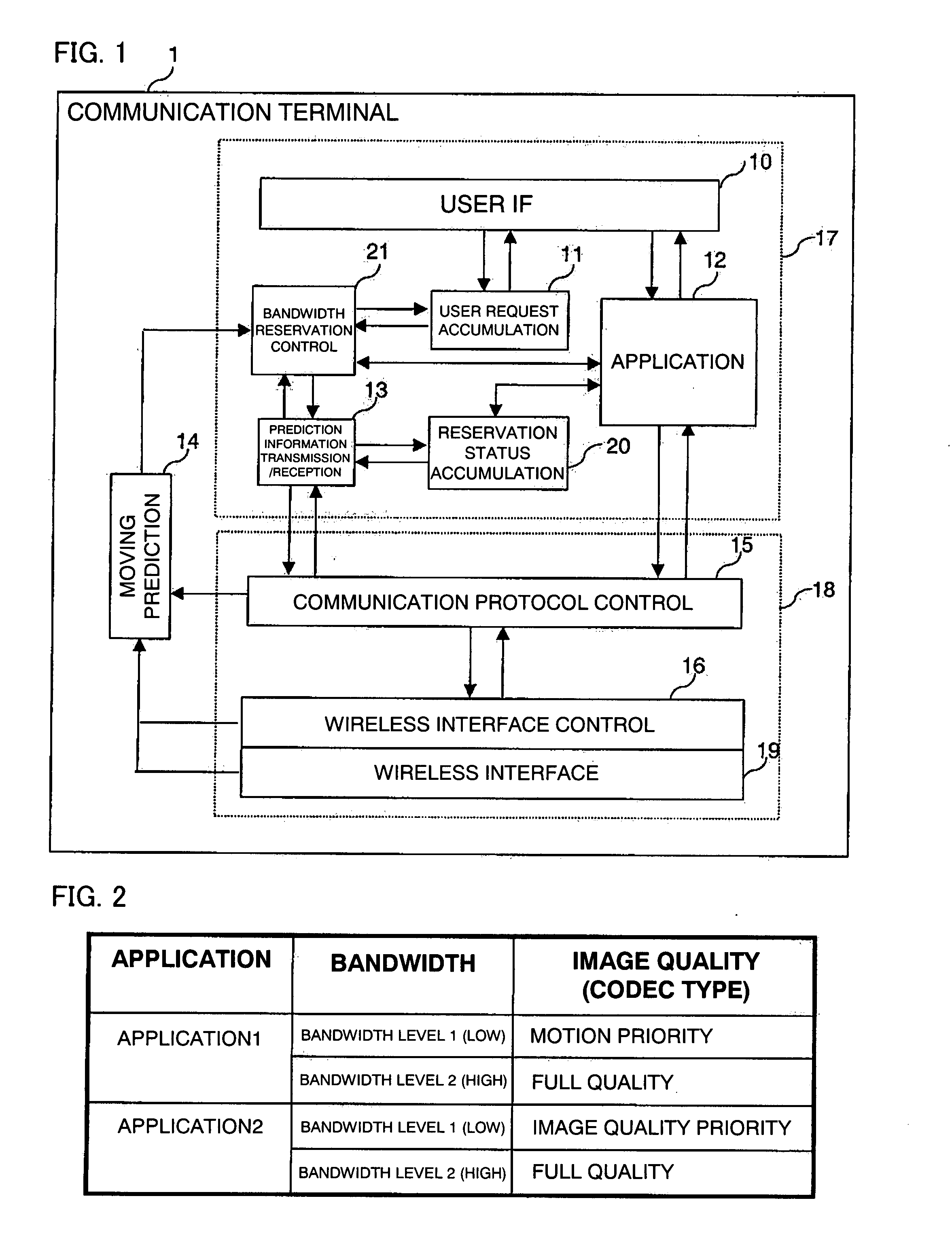
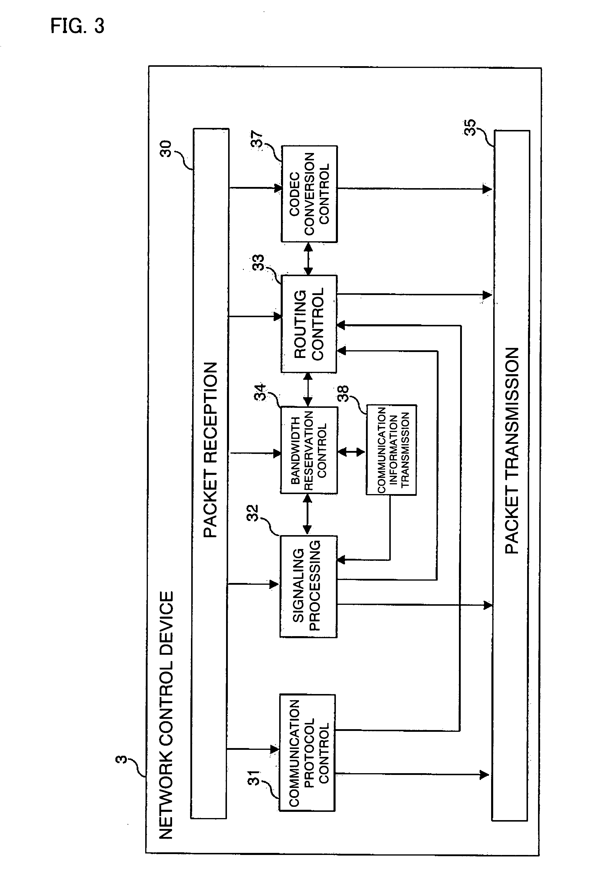
[0076]FIG. 1 illustrates the configuration of a communication terminal 1 of the first embodiment and FIG. 3 illustrates a network control device 3 of the first embodiment. Before description using these figures, an environment in which the network control device 3 and the communication terminal 1 according to the first embodiment of the invention are applied will be described.

[0077]FIG. 4 illustrates the structure of a communication network system representing the environment in which the communication terminal 1 and the network control device 3 according to the first embodiment are applied. The communication terminal 1 and a communication terminal 2 communicate with each other over the Internet 5. A network 6 is the home network for the communication terminal 1. A network 8 is the home network for the communication terminal 2.

[0078]Here, encoding method for communication data in the embodiment will be described. In the system shown in FIG. 4, the communication terminals 1 and 2 per...

second embodiment

[0131]The communication terminal 1, network control device 3 and data controlling method according to the second embodiment of the invention will be described below. The communication terminal 1 and the network control device 3 of the second embodiment are applied to the same communication network system as in the first embodiment (see FIG. 4).

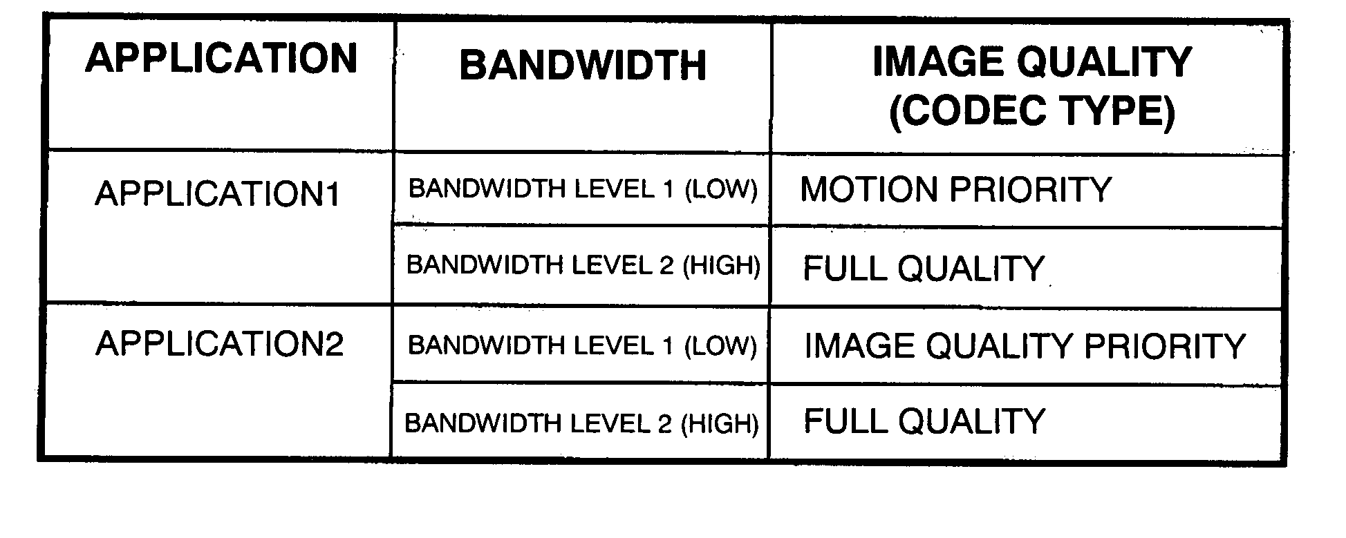
[0132]In the second embodiment of the invention, a user request about relationship between application quality and bandwidth is transmitted from the communication terminal 1 to the network control device 3. The network control device 3 accumulates user requests and makes bandwidth reservation based on user requests.

[0133]In the following, the configuration and operation of the communication terminal 1 and the network control device 3 according to the second embodiment of the invention will be described with reference to three examples of operation as in the first embodiment.

[0134]FIG. 13 illustrates the configuration of the communication termi...


PUM


Abstract

A communication terminal (1) comprises a wireless interface (19) for detecting intensity of radio wave that is received via a plurality of networks that use different communication schemes; a movement prediction unit (14) for predicting a destination network based on radio wave intensity detected by the wireless interface (19); and prediction information transmission unit (13) for transmitting a bandwidth reservation request that requests reservation of a bandwidth between a destination network control device (4) controlling communication connection in a destination network that is predicted to be the destination of the communication terminal and a network control device (3) to which the communication terminal is currently connected as well as transfer of currently communicated communication information to the destination network control device, to the network control device to which the communication terminal is currently connected. This enables smooth switching to a different network.

Description

TECHNICAL FIELD[0001]The present invention relates to data transmission control when a terminal moves across networks while performing communication.BACKGROUND ART[0002]In recent years, there has been an increasing variety of mobile networks such as public mobile networks, hot spots, and PHS networks within companies. When a communication terminal moves across different networks, it is required that the best communication quality for an application is ensured in a destination network and that time required for switching from one network to another is minimized.[0003]A well-known technique for switching between different IP networks is Mobile IP technique developed by Internet Engineering Task Force (IETF). In Mobile IP technique, when a communication terminal moves from one network to another, the terminal obtains a Care of Address (CoA) from a Foreign Agent (FA) for the destination network and registers the obtained address to its Home Agent (HA) that is provided in its home networ...

Claims


Application Information

Patent Timeline
IPC IPC(8): H04Q7/20H04Q7/38H04L47/2475H04W4/02H04W36/14H04W36/28H04W36/32H04W76/02
CPCH04W4/02H04W28/26H04L67/18H04W36/32H04W36/14H04L67/52
Inventor XU, MING QIANGTAKESHITA, SACHIKOAMISHIMA, MAKITAKEI, KENTARO
Owner XU MING QIANG
Learn More