Redundant switch mechanism for safety-critical applications in medical systems

a switch mechanism and safety-critical technology, applied in the field of safety switch arrangement for medical devices, can solve the problems of not necessarily the most failsafe or ergonomically correct solution, harm to a patient or operator,

Active Publication Date: 2008-06-05
GENERAL ELECTRIC CO
View PDF1 Cites 17 Cited by
  • Summary
  • Abstract
  • Description
  • Claims
  • Application Information

AI Technical Summary

Problems solved by technology

This button represents a single point of failure that could result in harm to a patient or operator if a malfunction were to occur.
To circumvent this problem in existing equipment, the operator is required to depress two separate buttons, which is not necessarily the most failsafe or most ergonomically correct solution.

Method used


Image

  • Redundant switch mechanism for safety-critical applications in medical systems
  • Redundant switch mechanism for safety-critical applications in medical systems
  • Redundant switch mechanism for safety-critical applications in medical systems

Examples


Embodiment Construction

[0020]In the following detailed description, reference is made to the accompanying drawings that form a part hereof, and in which is shown by way of illustration specific embodiments which may be practiced. These embodiments are described in sufficient detail to enable those skilled in the art to practice the embodiments, and it is to be understood that other embodiments may be utilized and that logical, mechanical, electrical and other changes may be made without departing from the scope of the embodiments. The following detailed description is, therefore, not to be taken in a limiting sense.

System Level Overview

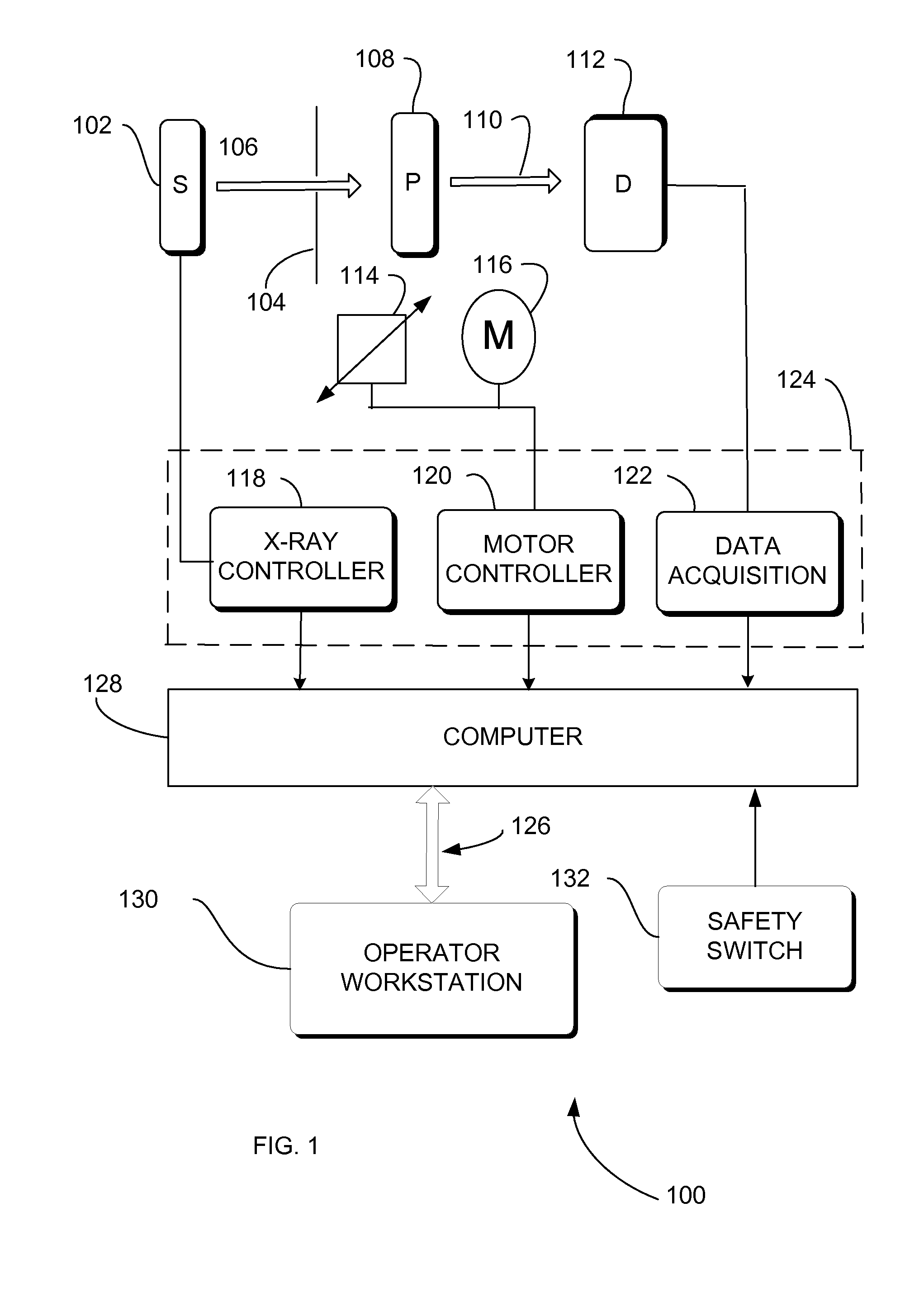
[0021]FIG. 1 is a block diagram that provides a system level overview. Embodiments are described as operating in a multi-processing, multi-threaded operating environment on a computer.

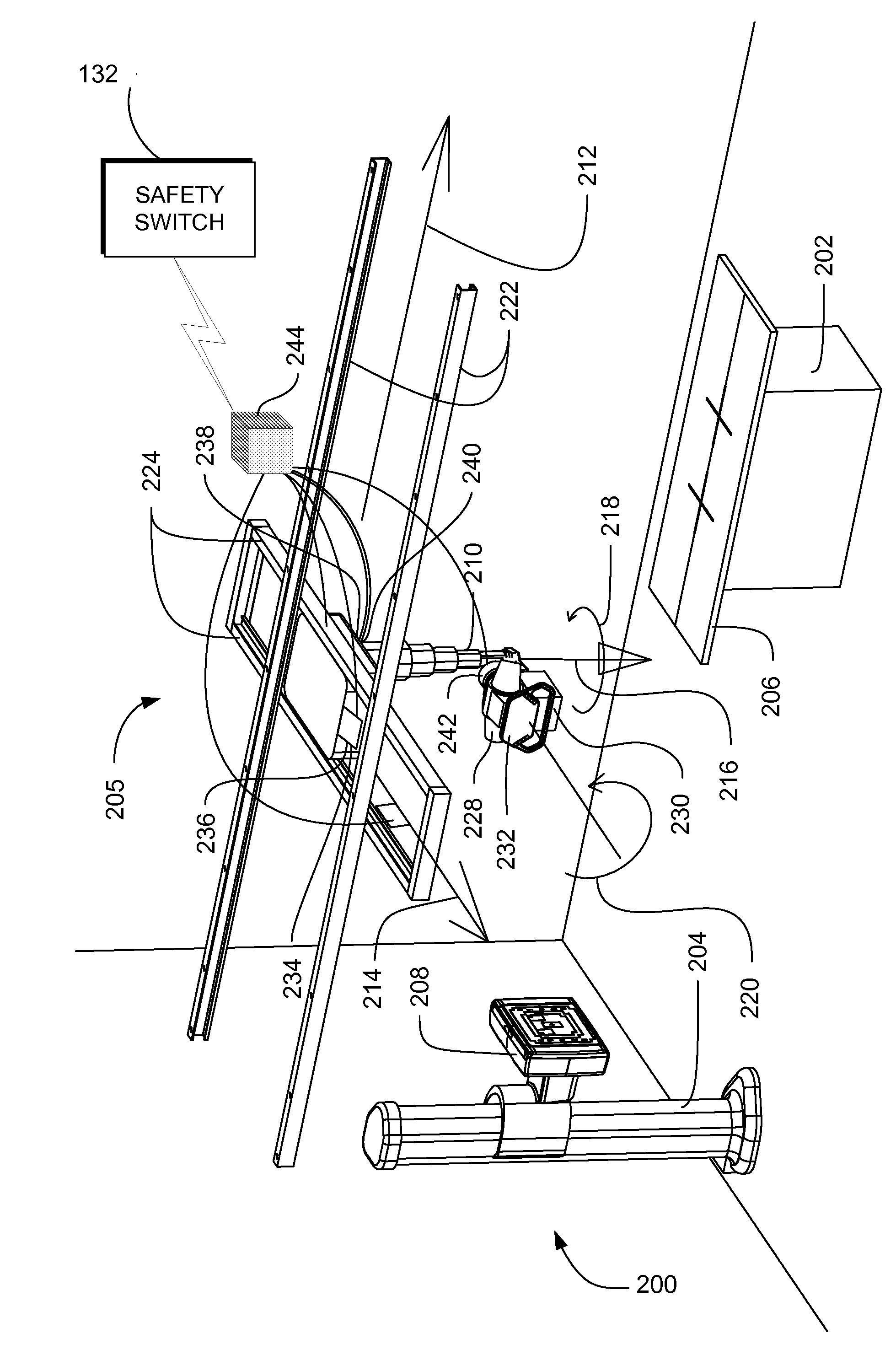
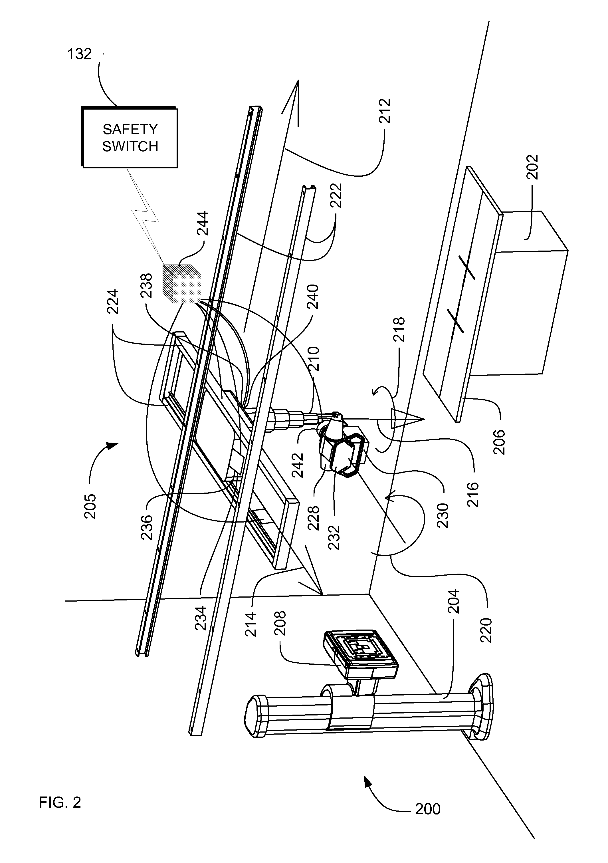
[0022]FIG. 1 illustrates diagrammatically an exemplary embodiment of a medical imaging system 100 for acquiring and processing image data. While the exemplary embodiment shows an X-ray imaging...


PUM


Abstract

Systems, methods and apparatus are provided through which a safety switch arrangement is assembled to prevent false activation of a subsystem in a medical system. In some embodiments, the safety switching arrangement comprises at least a first and a second type of switching element. In some embodiments, the first and the second type of switch each have an output that is processed by a processor, controller, or logic unit to produce an output signal for activating or deactivating a subsystem in the medical system.

Description

FIELD OF THE INVENTION[0001]This invention relates generally to a safety switch arrangement for medical devices, and more particularly to dual switch arrangement for preventing false activation of subsystems in a medical system.BACKGROUND OF THE INVENTION[0002]In many medical systems, including medical imaging systems, the positioning sub-systems contain one or more motorized axes. A button on the operator console can invoke motion on these axes. This button represents a single point of failure that could result in harm to a patient or operator if a malfunction were to occur.[0003]To circumvent this problem in existing equipment, the operator is required to depress two separate buttons, which is not necessarily the most failsafe or most ergonomically correct solution. For example, a dual-switch that uses two pressure-based switches could be tricked into activation if it was pressed too hard or if a heavy object was placed on it.[0004]For the reasons stated above, and for other reaso...

Claims


Application Information

Patent Timeline
Patent Type & Authority Applications(United States)
IPC IPC(8): H05G1/54
CPCA61B6/4464
Inventor PETERSON, MATTHEW B.BIELSKI, SCOTT A.STOPAR, KENNETH M.COOMBS, KEVIN A.BUTZINE, JONATHAN M.
Owner GENERAL ELECTRIC CO
Why Eureka
Try Eureka