Microphone package

a technology for microphones and packages, applied in the direction of piezoelectric/electrostrictive transducers, transducer types, and electrostatic transducers of semiconductor sensors, can solve the problems of reducing the quality of sound detection realized by the microphone chip, affecting so as to reduce the size of the sound hole of the housing and improve the quality of sound detection

Inactive Publication Date: 2008-06-05
YAMAHA CORP
View PDF3 Cites 39 Cited by
  • Summary
  • Abstract
  • Description
  • Claims
  • Application Information

AI Technical Summary

Benefits of technology

[0011]It is an object of the present invention to provide a microphone package that is improved in the quality

Problems solved by technology

In this type of microphone package, when dust enters into the cavity of the housing via the sound hole or when light is unexpectedly introduced into the housing so as to reach the microphone chip, erroneous operation may occur in the silicon condenser microphone, or microphone characteristics are varied.
This degrades the quality of sound detection realized by the microphone chip.
This type of semiconductor device is designed such that the semiconductor sensor chip is electrically connected to the amplifier via wires, whereas the joining portions at which the wires join the semiconductor sensor chip and the amplifier may likely corrode

Method used


Image

  • Microphone package
  • Microphone package
  • Microphone package

Examples


first embodiment

1. First Embodiment

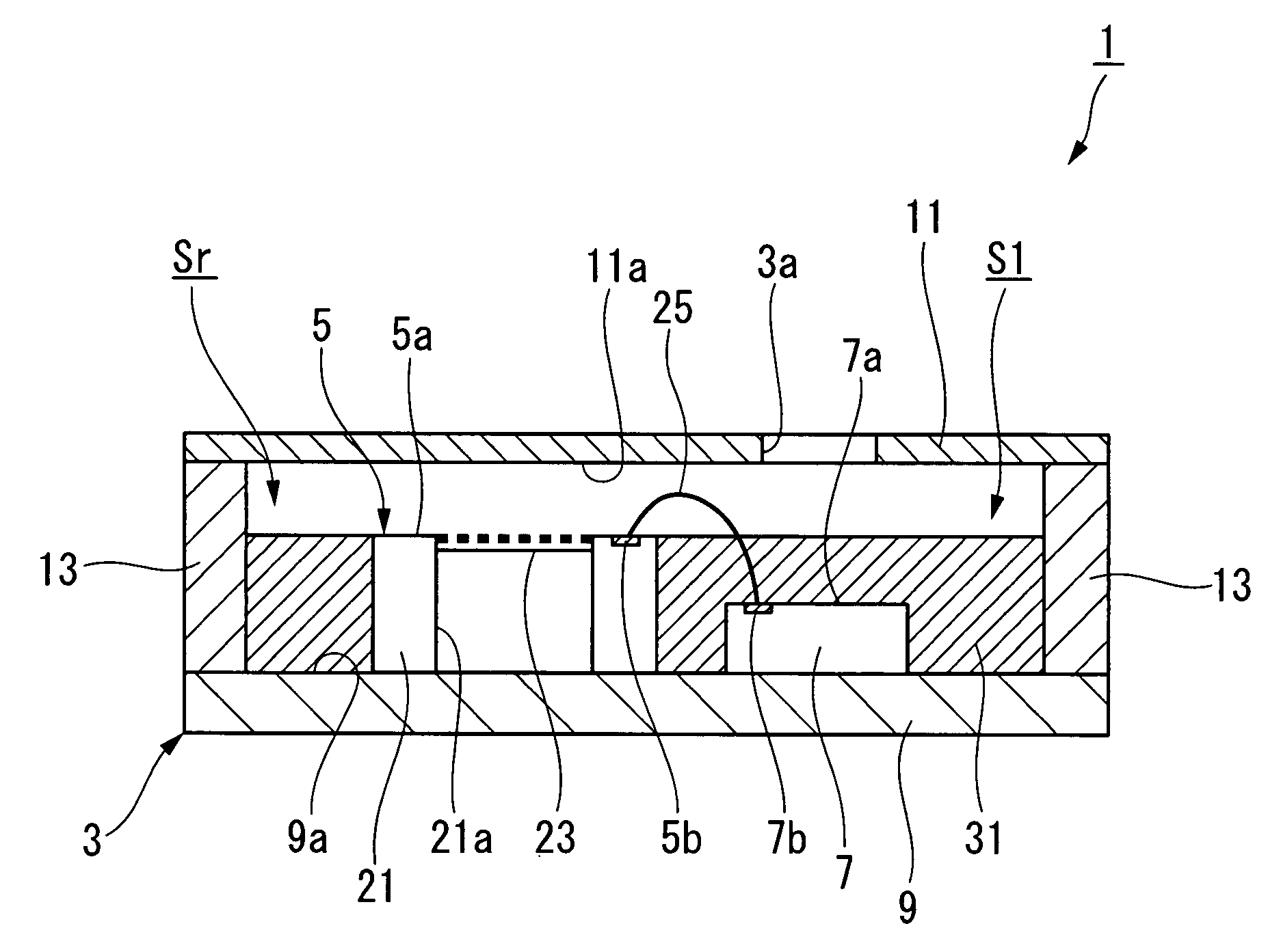
[0052]FIG. 1 shows a microphone package 1 in accordance with a first embodiment of the present invention. The microphone package 1 is constituted of a housing 3 having a cavity S1 and a sound hole 3a (allowing the cavity S1 to communicate with the exterior) as well as a microphone chip 5 and a LSI chip 7, both of which are arranged inside of the cavity S1.

[0053]The housing 3 is constituted of a substrate 9 having a mounting surface 9a, on which the microphone chip 5 and the LSI chip 7 are mounted, a top portion 11, which is distanced from the mounting surface 9a of the substrate 9 in the thickness direction, and a side wall 13, which is fixed to the circumferential periphery of an interior surface 11a of the top portion 11 positioned opposite to the mounting surface 9a of the substrate 9.

[0054]The substrate 9 is a multilayered wiring substrate in which electrical wiring (not shown) is laid, wherein the electrically wiring exposed on the mounting surface 9a is elec...

second embodiment

2. Second Embodiment

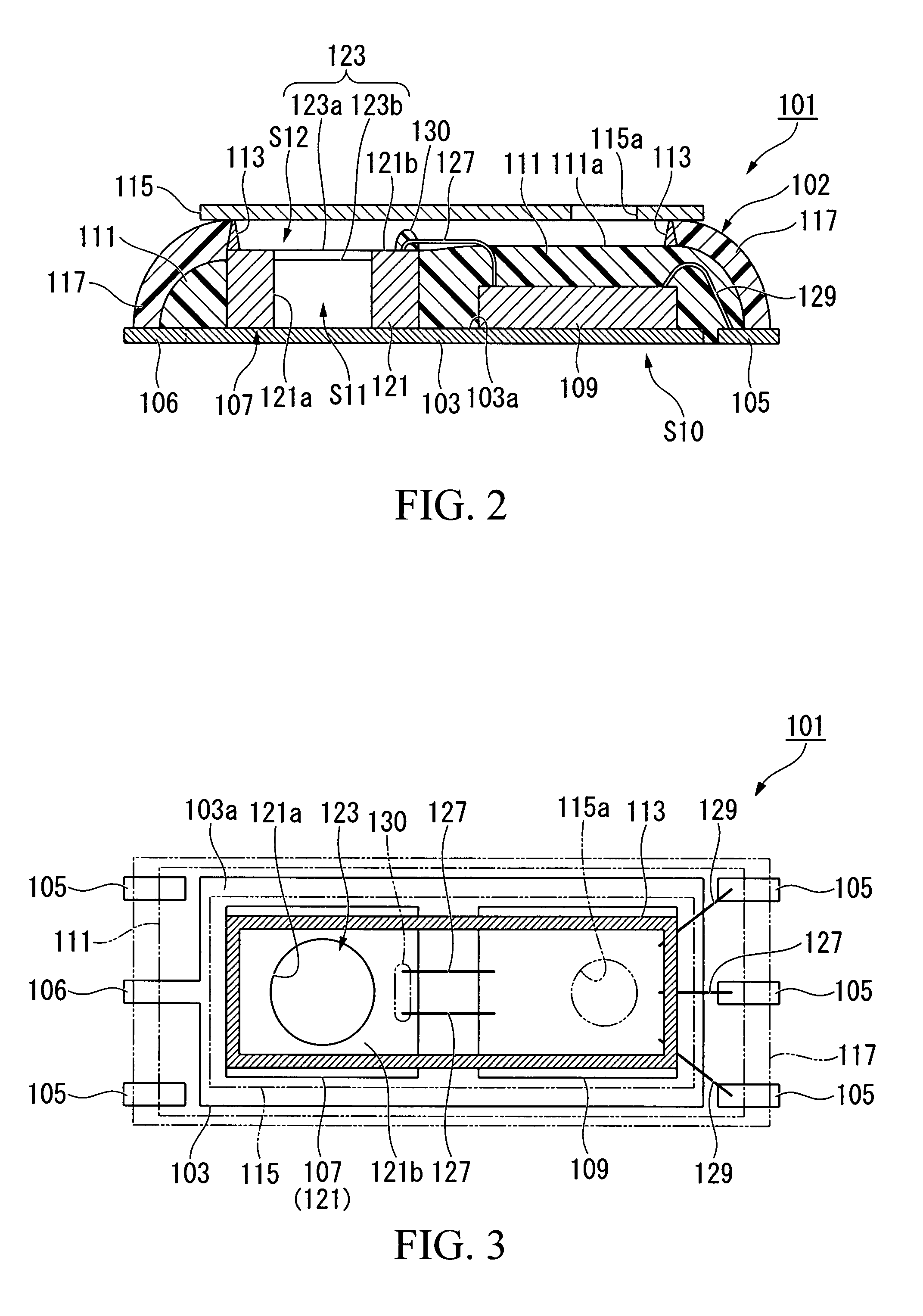
[0078]Next, a semiconductor device 101 according to a second embodiment of the present invention will be described with reference to FIGS. 2 to 9. As shown in FIGS. 2 to 4, the semiconductor device 101 is constituted of a substrate 103 composed of a metal, a plurality of metal leads 105 and 106 arranged in the periphery of the substrate 103, a semiconductor sensor chip 107 and a control circuit chip (or a LSI chip) 109, which are fixed onto a mounting surface 103a of the substrate 103, a resin sealing portion 111 formed in proximity to the mounting surface 103a of the substrate 103, a top portion (or a cover member) 115, which is fixed in position above the semiconductor sensor chip 107 and the control circuit chip 109 via a dam 113, and a resin molded portion 117 formed in the periphery of the resin sealing portion 111.

[0079]The leads105 and 106 are each aligned along the mounting surface 103a of the substrate 103. The lead 106 is interconnected to the substrate...


PUM


Abstract

A microphone package includes a housing having a cavity and a sound hole allowing the cavity to communicate with the exterior. A microphone chip is mounted on the mounting surface inside of the cavity. The sound hole is opened on the interior surface of the housing positioned opposite to the mounting surface. A resin sealing portion is formed to seal the surrounding area of the microphone chip and the mounting surface. Alternatively, a semiconductor sensor chip and a control circuit chip are mounted on the mounting surface inside of the cavity of the housing and are electrically connected together via bonding wires. Herein, the resin sealing portion entirely seals the control circuit chip and the first joining portions joining the first ends of the bonding wires, while a resin potting portion seals the second joining portions between the electrode pads and the second ends of the bonding wires.

Description

BACKGROUND OF THE INVENTION[0001]1. Field of the Invention[0002]The present invention generally relates to microphone packages encapsulating silicon condenser microphones. The present invention also relates to semiconductor devices incorporating pressure sensor chips such as sound pressure sensor chips as well as manufacturing methods of semiconductor devices.[0003]This application claims priority on Japanese Patent Application No. 2006-262039 and Japanese Patent Application No. 2007-163952, the contents of which are incorporated herein by reference.[0004]2. Description of the Related Art[0005]Japanese Patent Application Publication No. 2004-537182 teaches a microphone package encapsulating a miniature silicon condenser microphone, in which a microphone chip (for detecting sound) and a LSI chip (for controlling the microphone chip) are mounted on the mounting surface of a housing having a hollow cavity. The housing has a sound hole allowing the cavity to communicate with the exterio...

Claims


Application Information

Patent Timeline
IPC IPC(8): H04R11/04H01L21/00
CPCH04R1/2884H04R19/005H04R19/02H04R31/00H01L2224/48091H01L2224/48137H01L2924/3025H01L2924/00014H01L2924/00H01L2224/8592H01L2924/181H01L2924/16151H01L2924/00012
Inventor SATO, AKIYOSHISAKAKIBARA, SHINGOSUZUKI, JUNYA
Owner YAMAHA CORP
Why Eureka
Try Eureka