Adjustable cargo partition system for use in containers

a cargo partition and container technology, applied in the direction of cargo supporting/securing components, load transportation vehicles, railway components, etc., can solve the problems of increasing transportation costs, high cost, and complex structure of bulkheads and partitions, and achieve the effect of quick and easy positioning

Inactive Publication Date: 2008-06-05
PESSON RODNEY J
View PDF2 Cites 25 Cited by
  • Summary
  • Abstract
  • Description
  • Claims
  • Application Information

AI Technical Summary

Benefits of technology

[0019]In a further aspect of the present disclosure, a container for transporting cargo in a secured manner is described, wherein the container comprises a first wall, a second wall, a top and a bottom; a first e-track rail on a first wall and a second e-track rail on a second wall, spaced opposite the first e-track; and a temporary partition assembly selectively located within the container for separating the container into at least a first and second compartment; wherein the partition assembly is vertically adjustable and can be lockably attached to the first and second e-track, and wherein access to the cargo in the first compartment is prevented without first removing the temporary partition assembly, while access to cargo in the second compartment is unaffected by the presence of the temporary partition.

Problems solved by technology

As delivery proceeds, the truck trailer becomes partially emptied., thereby increasing transportation costs.
However, these partitions obstruct and slow the loading process.
However, these known doors, bulkheads and partitions are often structurally complex, expensive, difficult to position, heavy, and must be moved each time the goods contained behind the partitions are to be loaded or unloaded.
While some bulkheads or partitions have been described having doors that can be opened, a majority of the partitions are substantially solid, and it is therefore difficult to know precisely what is behind the bulkhead without first moving it.
Additionally, these known partitions or bulkheads often feature heavy mounting hardware and, in order to be moved, are hinged such that the entire bulkhead or partition is lifted, much in the manner of an overhead garage door, and then positioned along the roof of the trailer when not in use.
Such doors are often difficult and expensive to repair, and also can represent a potential safety hazard should the door hardware fail and the door come down unexpectedly.
Often, however, operators of such transporting and delivering operations, end up not using or rejecting the use of such partitions due to the partitions being either awkward or difficult and inconvenient to use.
This in turn subjects the non-separated cargo to problems with off-loading of packages, inefficient use of space within the transport container, and the like.
For example, with respect to the rigid partitions or bulkheads, such partitions are often not easily re-positional along the length of a trailer, making their use to close off spaces within the trailer ineffective or strenuous.
With respect to the “curtain” or strip-type blanket dividers, while they may be efficient for on-loading and off-loading individual packages or small numbers of packages, they can be a hindrance to bulk applications.
Without a facile, easily operated structure to enable the movement of the curtain along the trailer width and length, there is a tendency for the operator to fail to use the curtain-type divider, or not use it properly.
Another problem in the shipping industry is the shifting and undesirable movement of loads within the transport container.
Items and boxes can move around the interior space of a carrier container, which not only risks damaging the merchandise being transported, especially fragile items such as electronics or impact sensitive food products like potato chips, but these shifts in load weight within the container can shift the weight of the transport vehicle.
This latter effect may in turn cause an unbalanced load to such a degree that the tractor trailer or other transport means rolls or tips, in turn threatening not only the life of the operator of the transport, but the life of others surrounding the transport who are totally unaware of the danger that they can be in.

Method used


Image

  • Adjustable cargo partition system for use in containers
  • Adjustable cargo partition system for use in containers
  • Adjustable cargo partition system for use in containers

Examples


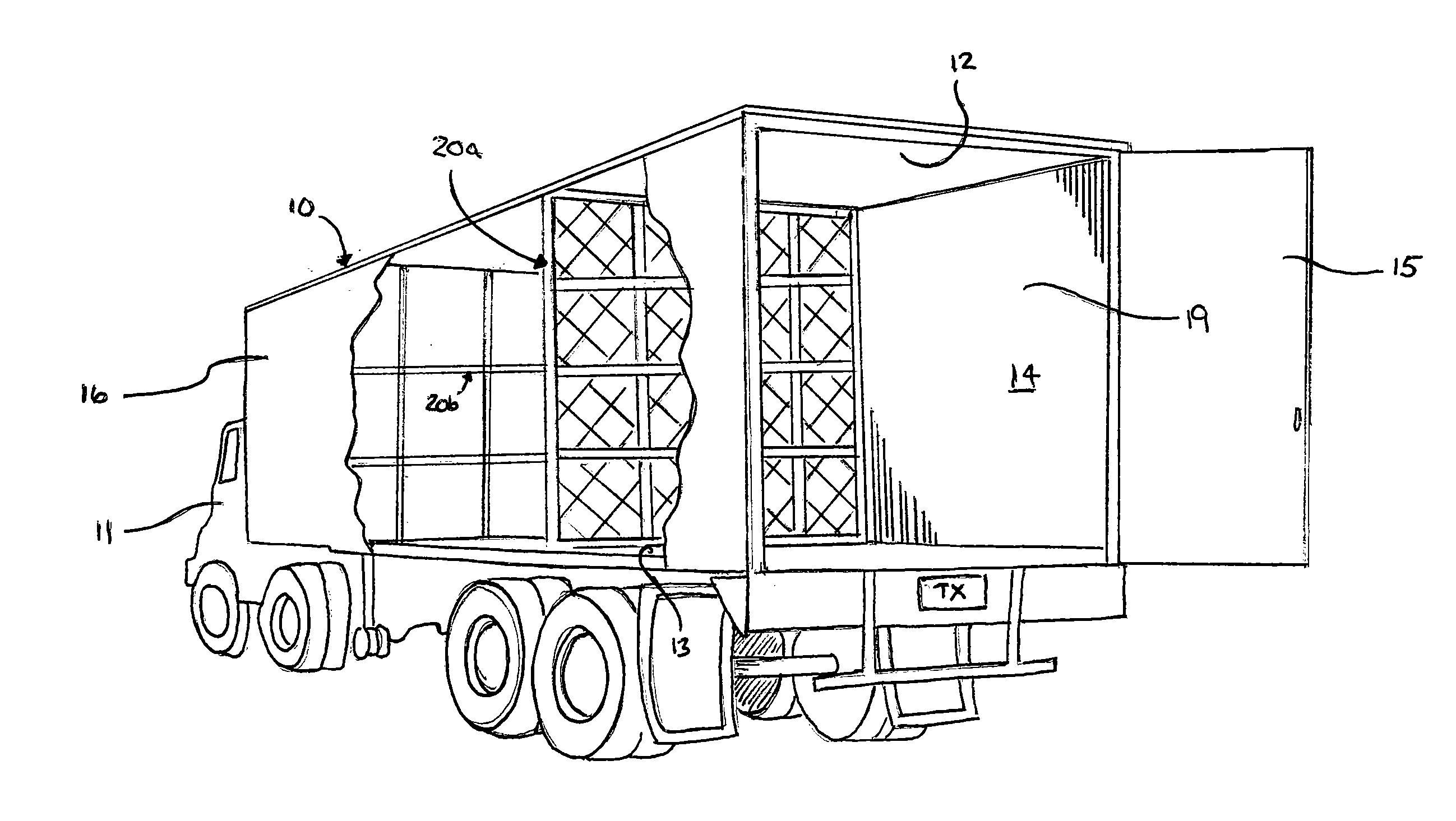
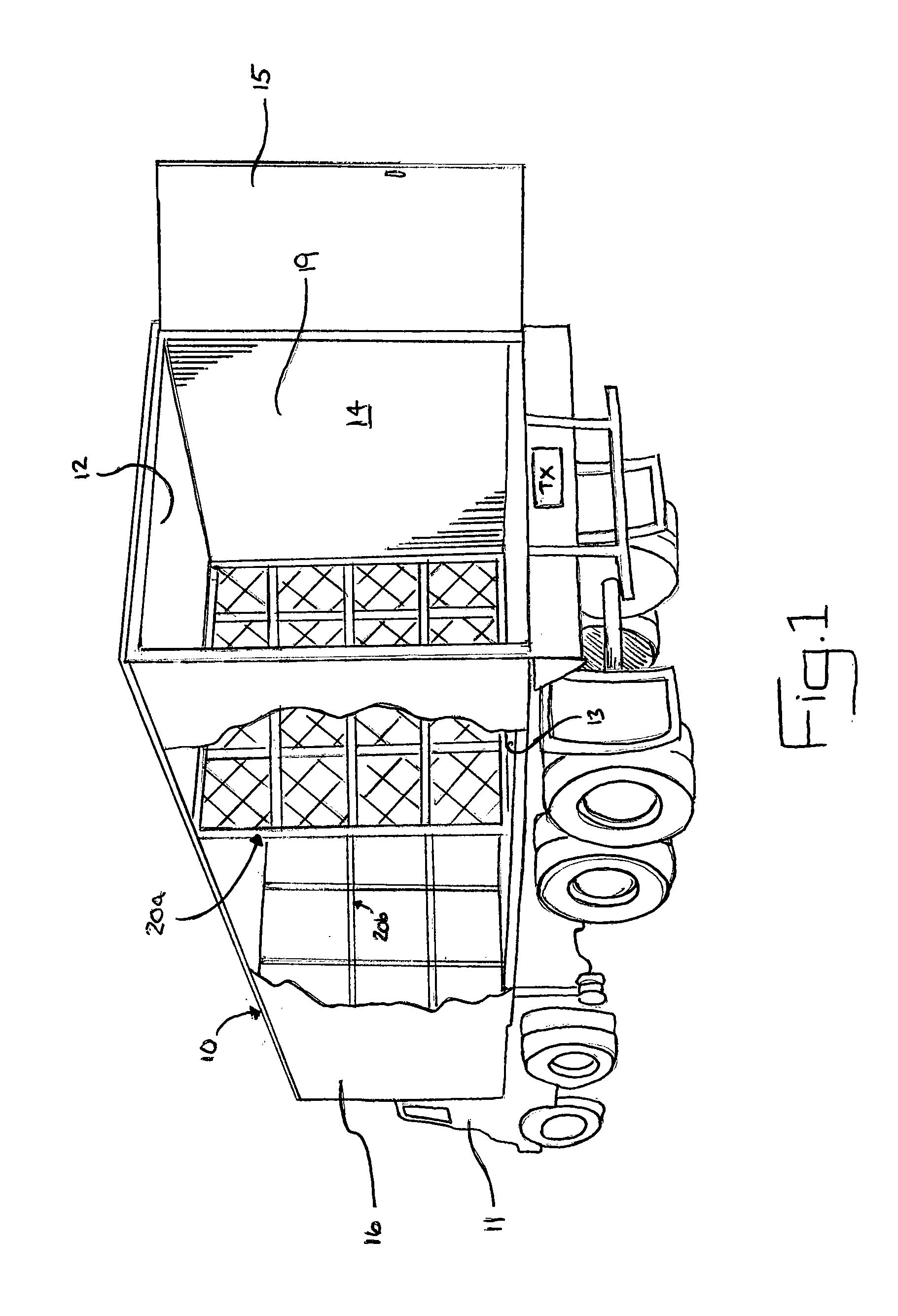
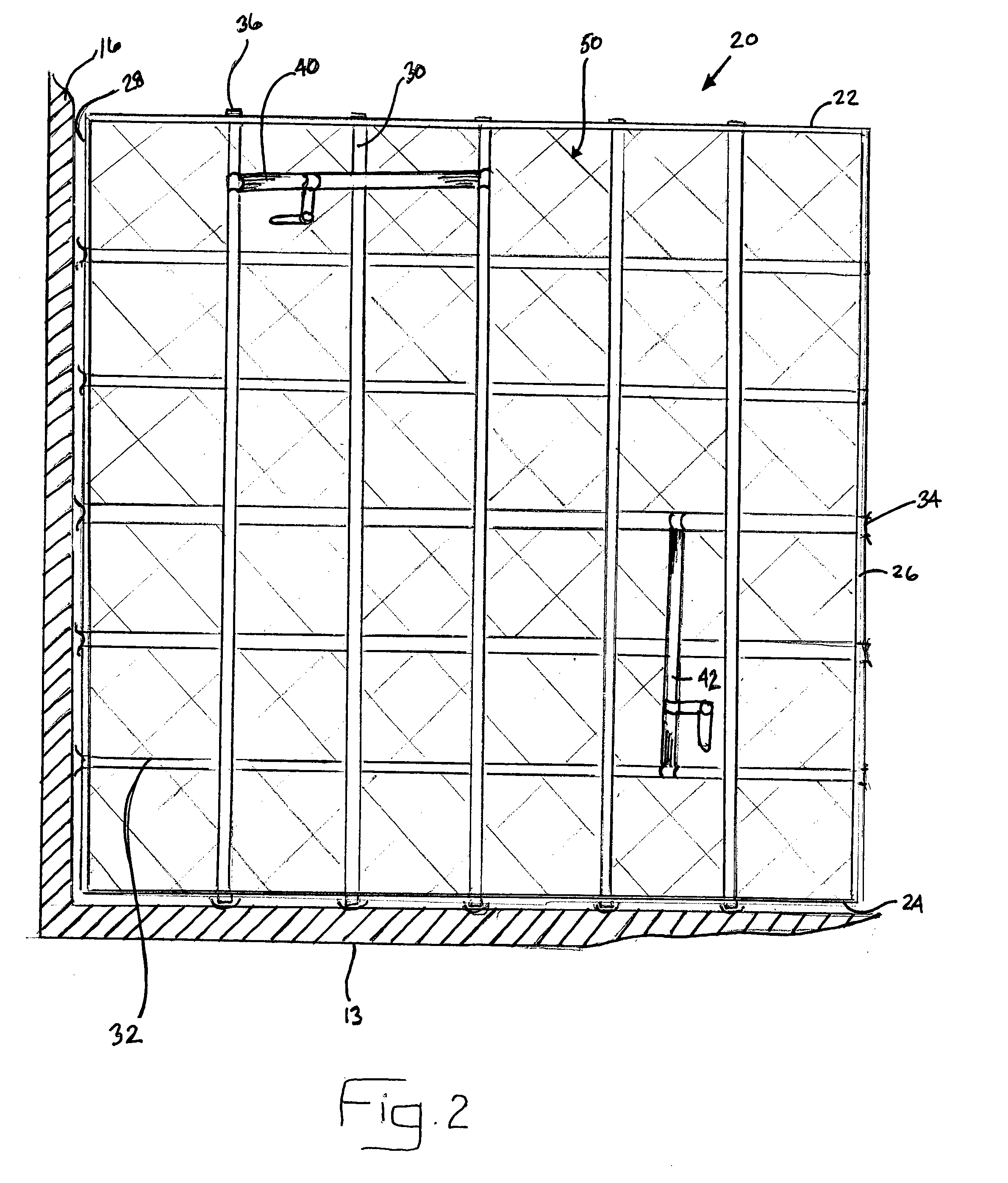
Embodiment Construction

[0037]The Figures described above and the written description of specific structures and functions below are not presented to limit the scope of what Applicants have invented or the scope of the appended claims. Rather, the Figures and written description are provided to teach any person skilled in the art to make and use the inventions for which patent protection is sought. Those skilled in the art will appreciate that not all features of a commercial embodiment of the inventions are described or shown for the sake of clarity and understanding. Persons of skill in this art will also appreciate that the development of an actual commercial embodiment incorporating aspects of the present inventions will require numerous implementation-specific decisions to achieve the developer's ultimate goal for the commercial embodiment. Such implementation-specific decisions may include, and likely are not limited to, compliance with system-related, business-related, government-related and other c...


PUM


Abstract

A repositionable partition or wall assembly for use within a storage or cargo transport compartment, for dividing the compartment into sub-compartments and allowing for the secured transport of cargo that does not occupy the entire container, is described. The partition or wall assembly comprises at least two vertically extending stiles, and a retaining member or means extending between the at least two vertically extending stiles, wherein the partition or wall assembly is vertically and horizontally adjustable within the compartment. Also provided are methods and systems of secured transportation of partial or full cargo loads within such cargo transportation compartments or containers.

Description

CROSS REFERENCE TO RELATED APPLICATIONS[0001]The present application claims priority to U.S. Provisional Patent Application Ser. No. 60 / 864,499 filed Nov. 6, 2006, the contents of all of which are incorporated herein by reference in their entirety.STATEMENT REGARDING FEDERALLY SPONSORED RESEARCH OR DEVELOPMENT[0002]Not applicable.REFERENCE TO APPENDIX[0003]Not applicable.BACKGROUND OF THE INVENTION[0004]1. Field of the Invention[0005]This disclosure relates generally to adjustable wall assemblies for use with storage or transportation containers, and more particularly to adjustable partition assemblies for use in dividing the interior storage compartment of a storage or transportation container into a plurality of subcompartments so as to better secure loads within the transportation container.[0006]2. Description of the Related Art[0007]Transportation vehicles such as trucks, trailers, railroad cars, and other freight vehicles have long utilized assemblies, such as walls or bulkhea...

Claims


Application Information

Patent Timeline
Patent Type & Authority Applications(United States)
IPC IPC(8): B61D45/00
CPCB61D45/006B60P7/14
Inventor PESSON, RODNEY J.
Owner PESSON RODNEY J
Why Eureka
Try Eureka