[0007]The present invention was developed to further resolve these drawbacks. Thus, it is an important object of the present invention to provide a battery pack and method of manufacture that reliably prevents shift in insulating cover position during molded resin region formation and reliably prevents destruction of the safety valve by the molded resin region, and in addition prevents twisting strength degradation by accurately inserting the insulating cover in proper position.
[0009]The present invention prevents shift in the position of the insulating cover during molded resin region formation, and reliably prevents destruction of the safety valve by the molded resin region. It also inserts the insulating cover in an precise position in the molded resin region to achieve the characteristic that degradation in twisting strength can be prevented. This is because a projection that protrudes towards an inner surface of the mold cavity, which forms the molded resin region, is provided on the surface of the insulating cover layered on the battery. The battery pack is fabricated by injecting
synthetic resin into the mold cavity with the projection pressed upon by the mold to tightly secure the insulating cover on the surface of the battery. In the battery pack core secured in the mold cavity, the insulating cover is retained in a
fixed position by pressure from the mold on the insulating cover projection. With the projection of the insulating cover pressed by the mold, the insulating cover tightly contacts the surface of the battery secured in the mold. The
assembly is retained in this configuration while molten synthetic resin is injected into the mold cavity. Therefore, synthetic resin injected into the mold cavity does not shift the position of the insulating cover. In particular, the insulating cover does not become separated from the surface of the battery and molten synthetic resin does not ingress between the insulating cover and the battery. As a result, synthetic resin does not ingress between the insulating cover and the battery, does not ingress into the safety valve exhaust outlet, and does not damage the safety valve.
[0010]Since the insulating cover projection is pressed upon by the mold when the battery pack core is secured in the mold cavity, the position of the insulating cover is not shifted by the injected synthetic resin. Therefore, the insulating cover is inserted in a precise position in the molded resin region formed in the mold cavity. A structure that insert molds the insulating cover in a precise position in the molded resin region can improve twisting strength of the fabricated unit. The reason for this is understood by assuming an insulating cover is insert molded in a shifted position in the molded resin region and part of the insulating cover is either exposed outside the molded resin region or is extremely close to the surface of the molded resin region. In this situation, the insulating cover will deform to move away from the battery if a twisting force is applied to the battery pack having a locally thinned molded resin region.
[0012]Further, in the battery pack core 10
assembly step of the method of manufacture of the present invention, a circuit board 3 can be disposed on the projection 15 of the insulating cover 4, 54. In the resin injection process step, synthetic resin can be injected into the mold cavity 31 with the mold 30 pressing the insulating cover 4, 54 into
close contact with the battery 2 surface via the intervening circuit board 3. This method can form the molded resin region 1 with the battery pack core 10 secured in the mold cavity 31 and both the insulating cover 4, 54 and the circuit board 3 retained in precise positions. This is because both the insulating cover 4, 54 and the circuit board 3 are pressed upon by the mold 30 to avoid any shift in position. Consequently, in a battery pack manufactured by this method, both the insulating cover 4, 54 and the circuit board 3 can be insert molded in a precise positions in the molded resin region 1.
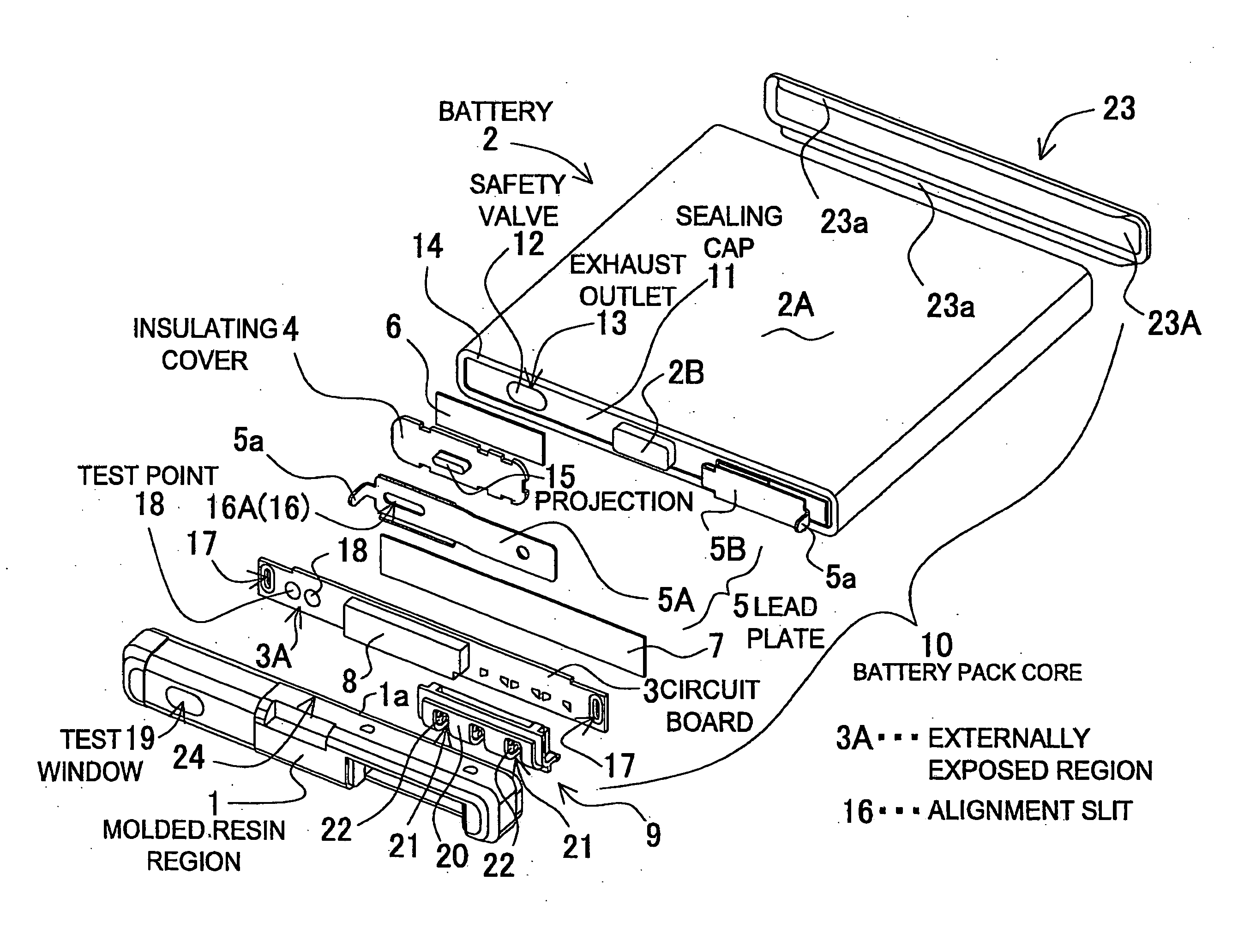
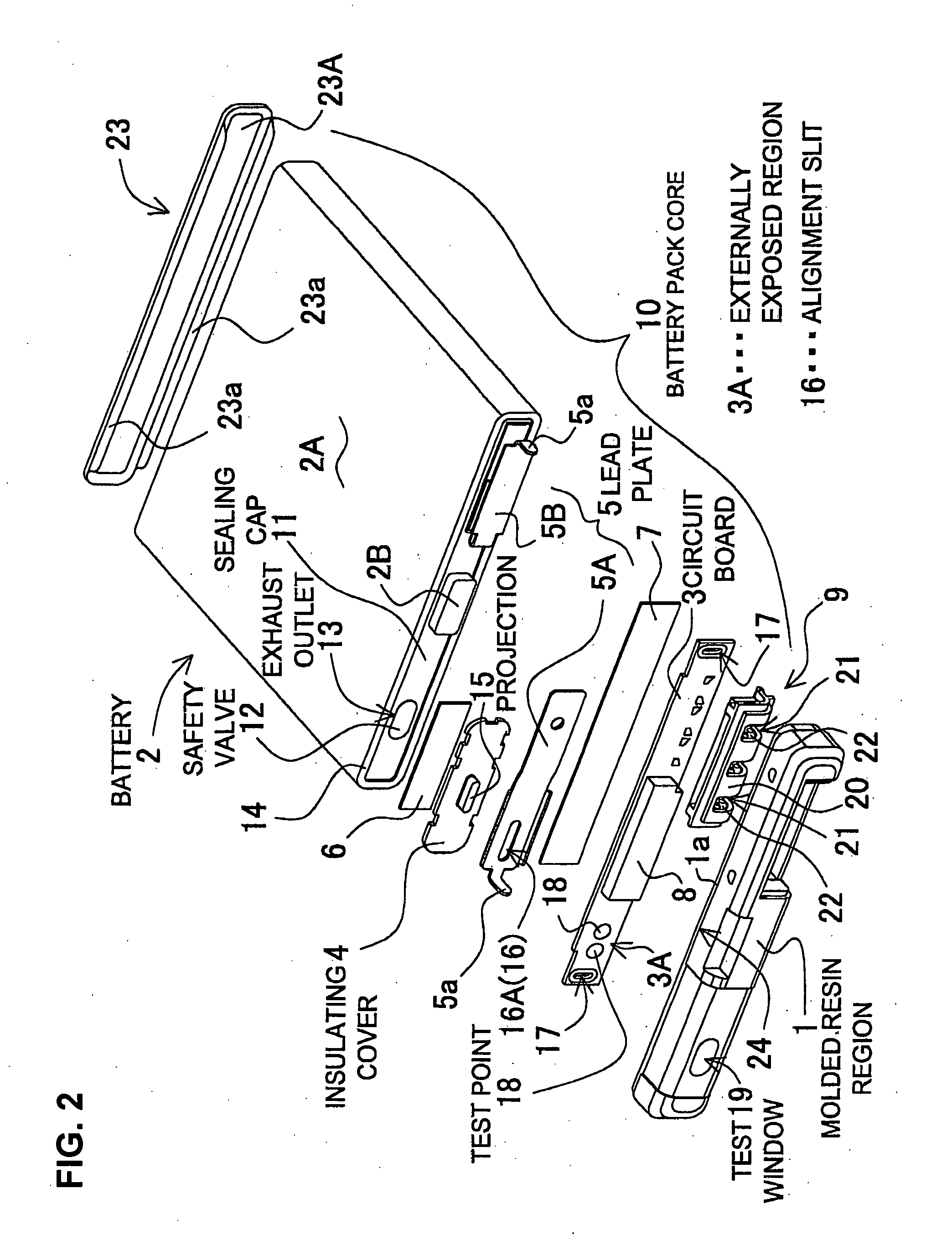
[0014]The battery pack of the present invention is provided with a battery 2 having a safety valve 12, an insulating cover 4, 54 disposed in a position opposite the exhaust outlet 13 of the safety valve 12 of the battery 2, and a molded resin region 1 attached to the battery 2 while inserting the insulating cover 4, 54. The insulating cover 4, 54 is provided with a projection 15 on its surface that is pressed in a direction towards the surface of the battery 2 by the mold 30, which forms the molded resin region 1. In this battery pack, with the projection 15 pressed by the mold 30 and the battery pack core 10 secured in the mold 30, the insulating cover 4, 54 can be retained in a precise position. As a result, the insulating cover 4, 54 can be inserted in a precise position in the molded resin region 1 formed under these conditions.
[0017]Further, the battery pack of the present invention can be configured with a circuit board 3 provided with a
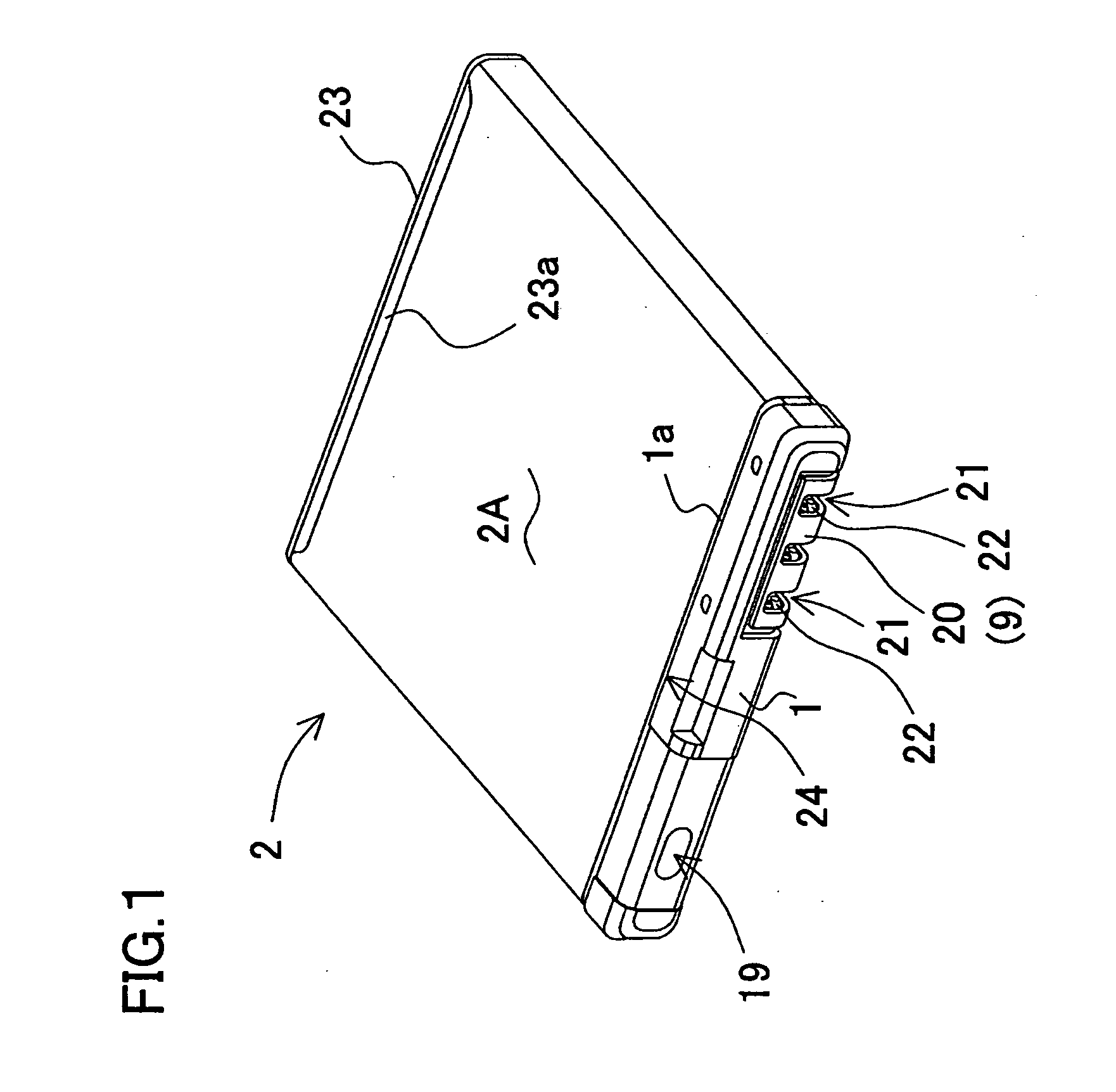
test point 18 on an externally exposed region 3A of the front surface, which is exposed outside the molded resin region 1. The backside of the externally exposed region 3A of the circuit board 3 can be established as a pressure region 3B that presses the projection 15 of the insulating cover 4, 54. The battery pack can be configured with a test window 19 provided in the molded resin region 1 to
expose the
test point 18 to the outside at the externally exposed region 3A of the circuit board 3. In this battery pack configuration, the externally exposed region 3A of the circuit board 30 can be pressed by the mold 30 that forms the test window 19, and the projection 15 of the insulating cover 4, 54 can in turn be pressed by the pressure region 3B provided on the backside of the externally exposed region 3A allowing the assembly to be secured in a
fixed position. With this configuration, the mold 30 that provides the test window 19 in the molded resin region 1 can dispose both the circuit board 3 and the insulating cover 4, 54 in fixed positions. Consequently, the circuit board 3 and the insulating cover 4, 54 can be inserted in precise positions in the molded resin region 1, and this can be done with the mold 30 that forms a test window 19 in the molded resin region 1 to
expose the
test point 18 to the outside.

