Driving Rod For The Piston Of A Reciprocating Compressor

Inactive Publication Date: 2008-06-12
WHIRPOOL SA
View PDF13 Cites 23 Cited by
  • Summary
  • Abstract
  • Description
  • Claims
  • Application Information

AI Technical Summary

Benefits of technology

[0019]Due to the dimensioning limitations of the cross-section of the driving rods of the reciprocating compressors with a linear or rotary motor, it is the object of the present invention to provide a driving rod presenting a construction that allows obtaining a flexibility, in at least one transversal direction, as well as an axial rigidity which can comply with the requirements of the compressor project regardless of the length defined for the driving rod.
[0020]The driving rod proposed by the present invention offers a simple solution that is easy to implement in the construction of reciprocating compressors, particularly those of the hermetic type used is refrigeration systems of household electric appliances in which the piston is designed to be axially displaced in a reciprocating movement inside a compression chamber, without being submitted to transversal reaction forces of the cylinder block caused by the acceptable geometrical or assembly errors of the component parts involved, but which are sufficiently relevant to cause friction that abbreviates the useful life of the compressor.
[0021]In order to attain the object cited above, the present driving rod comprises a bundle of “n” rods arranged side by side along the axis of the driving rod, each rod presenting a cross-section that is dimensioned and configured to impart to the driving rod, jointly with the other rods, an axial rigidity sufficient to transmit the reciprocating forces between the driving means and the piston, and a flexibility, in at least one transversal direction to the axis of the driving rod, sufficient to absorb, at least substantially, the forces applied to the piston, in said transversal direction, by both the driving rod and the driving means in the region of the compression chamber.
[0022]According to the solution proposed by the invention, the number and the cross-section of the rods that form the driving rod can be defined to impart to the latter optimized axial rigidity and transversal flexibility so that the reciprocating movement of the piston inside the compression chamber of the cylinder block occurs with little or no friction that abbreviates the useful life of the compressor.

Problems solved by technology

As known, the transversal reaction forces of the cylinder block against the piston can provoke excessive friction between the piston and the cylinder block, leading to an increase of energy consumption, consequently reducing the efficiency of the compressor, and to an accelerated wear of the components submitted to high friction levels, reducing the useful life of the compressor.
However, in use, said axes can become misaligned and thus undesirable transversal reaction forces may occur between the piston 20 and the cylinder block 10 by reason of some constructive characteristics inherent to the compressors, such as the geometrical errors in the construction of the helical springs and the transversal rigidity thereof when they are axially and elastically deformed.
Besides the aspects above, one should consider the fact that misalignments commonly occur in the construction and assembly of mechanical components, as perfection is not usually reached in terms of dimensions and forms of the different components of a mechanical device.
Said prior art solution do not permit an adequate flexibility in the dimensioning of the driving rod in relation to compressors in which the axial force to be transmitted or supported by the driving rod requires a cross-section area for the latter which hinders, in the length available for the single-piece driving rod, the latter from presenting the desired transversal flexibility.
This is a complex construction, requiring the provision of the pneumatic bearing to maintain the piston adequately centralized in the compression chamber.
However, due to the fact of being spaced apart, said prior art multiple rods do not absorb transversal forces produced by angular misalignments of the axis of the driving means in relation to the axis of the compression chamber.
As illustrated in FIG. 2 of the appended drawings, the reciprocating compressors with a connecting rod-crankshaft mechanism driven by a rotary motor also present problems related to geometrical and assembly errors.
These reaction forces FR, acting mainly in the direction of the articulating pin 21 of the piston 20, tend to produce undesirable levels of friction between the piston 20 and the cylinder block 10, increasing the consumption of energy in the operation of the compressor as well as the wear of the mutually frictional parts, reducing the reliability and the useful life of the machine.
While being of low cost and easy to execute, said construction, as already mentioned in relation to the driving rod of the linear motor compressors, makes the dimensioning of the cross-section a problematic task due to the length limitations of the driving rod and to the degree of transversal flexibility required to reduce the transmission of moments to the piston 20 to desirable levels.

Method used


Image

  • Driving Rod For The Piston Of A Reciprocating Compressor
  • Driving Rod For The Piston Of A Reciprocating Compressor
  • Driving Rod For The Piston Of A Reciprocating Compressor

Examples


Embodiment Construction

[0039]As already mentioned, the construction of the driving rod of the present invention is designed to be applied to reciprocating compressors driven by a linear motor or by a rotary motor.

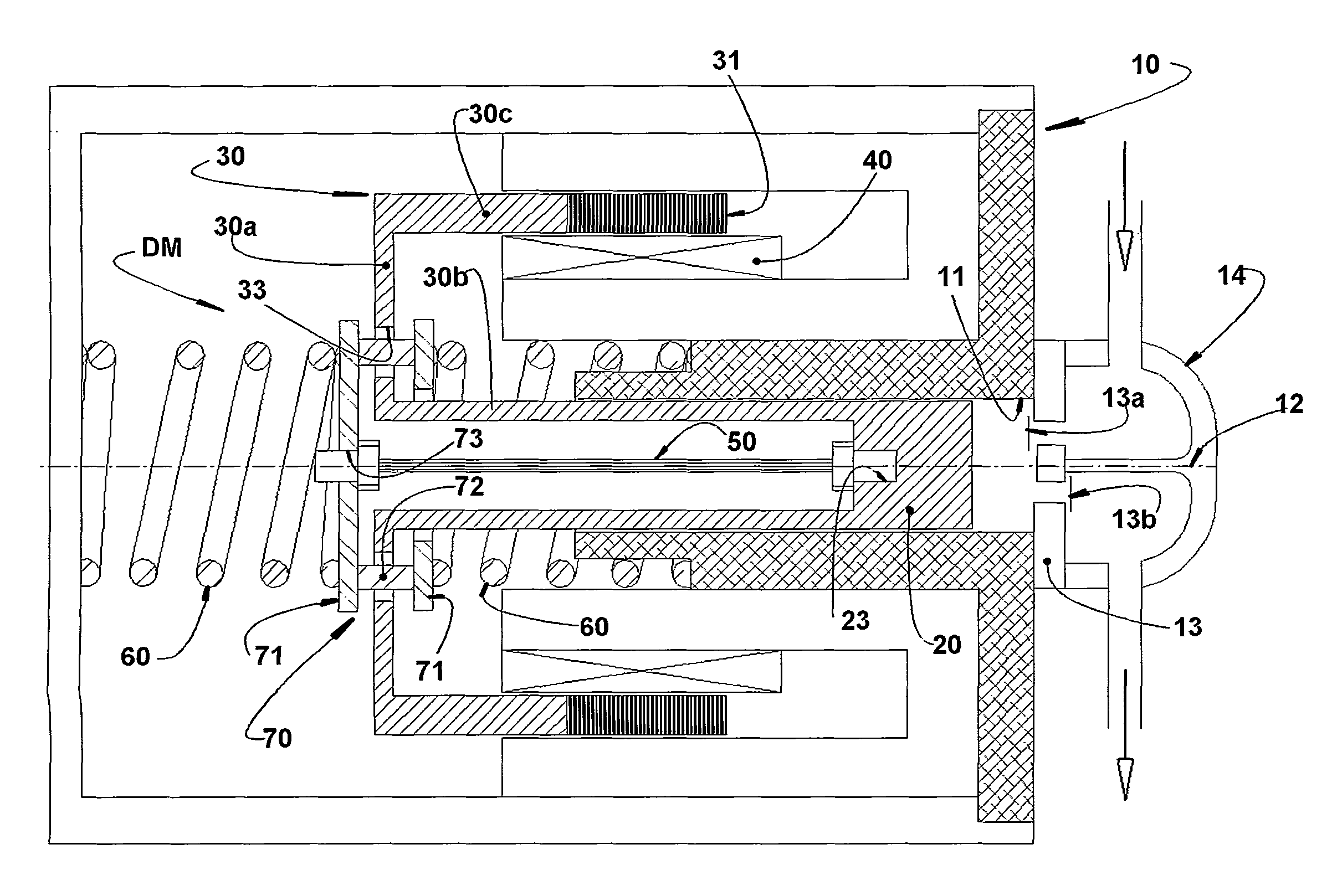
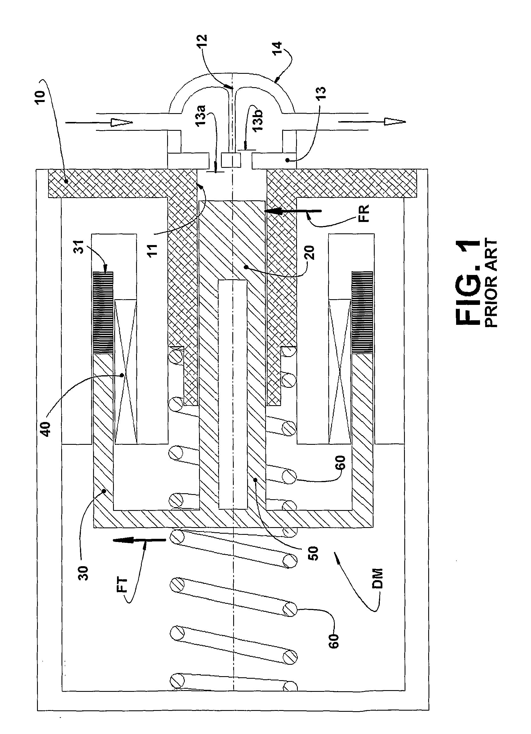
[0040]FIG. 3 illustrates, basically, the same elements that constitute a reciprocating compressor with a linear motor, contained in FIG. 1 and identified by the same reference numbers, constructive differences existing only in relation to the construction and assembly of the driving rod 50.

[0041]According to FIG. 3, the driving means DM is defined by an actuator 30 and by a pair of springs 60, the actuator 30 comprising a basic structure 30a, transversal to the axis 12 of the compression chamber 11 and incorporating an internal tubular projection 30b, rigidly secured to the piston 20, and an external tubular projection 30c that carries the magnetic element 31, the driving rod 50 being constructed so as to have an end secured to the piston 20 and an opposite end secured to a support 70 to which ar...


PUM


Abstract

A driving rod for the piston of a reciprocating compressor of the type that comprises: a cylinder block defining a compression chamber; a piston reciprocating within the compression chamber; a driving means to apply reciprocating forces to the piston; and a driving rod disposed between the piston and the driving means and comprising a number, greater than 1, of rods disposed side by side along the axis of the driving rod and each presenting a cross-section that is dimensioned and configured to impart to the driving rod, jointly with the other rods, a required axial rigidity and a flexibility, in at least one direction transversal to the axis of the driving rod, sufficient to absorb, at least substantially, the forces exerted on the piston by the driving rod and by the driving means.

Description

FIELD OF THE INVENTION[0001]The present invention refers to a driving rod to be applied to a reciprocating compressor with an electric motor of the rotary or linear type, said driving rod being constructed to operatively couple a driving means to a piston to be reciprocated in the interior of a compression chamber of the compressor, according to the axis of said chamber.PRIOR ART[0002]The reciprocating compressors that are driven by a rotary or linear electric motor generally comprise a cylinder block defining, internally, a compression chamber inside which axially reciprocates a piston coupled to a driving means mounted to the cylinder block and operatively associated with the electric motor of the compressor.[0003]The piston is coupled to the driving means so as to allow forces to be transferred therebetween and to make the piston move inside the compression chamber according to an axial direction coinciding with the axis of said compression chamber in order to minimize the transv...

Claims


Application Information

Patent Timeline
IPC IPC(8): F04B53/14
CPCF04B35/045Y10T74/2144F04B39/0022F04B39/00
Inventor LILIE, DIETMAR ERICH BERNHARDBERWANGER, EGIDIOPUFF, RINALDOFELDMANN, ALBERTO BRUNO
Owner WHIRPOOL SA
Why Eureka
Try Eureka