Cutting apparatus with a cutting tip sensor

Inactive Publication Date: 2008-06-12
BRADY WORLDWIDE INC
View PDF22 Cites 7 Cited by
  • Summary
  • Abstract
  • Description
  • Claims
  • Application Information

AI Technical Summary

Benefits of technology

[0007]A general objective of the present invention is to provide a cutting system that does not require manual adjustments in order to change a blade depth or obtain reliable cut output.

Problems solved by technology

The cutting blades in these prior art cutting systems are subject to wear requi

Method used


Image

  • Cutting apparatus with a cutting tip sensor
  • Cutting apparatus with a cutting tip sensor
  • Cutting apparatus with a cutting tip sensor

Examples


Embodiment Construction

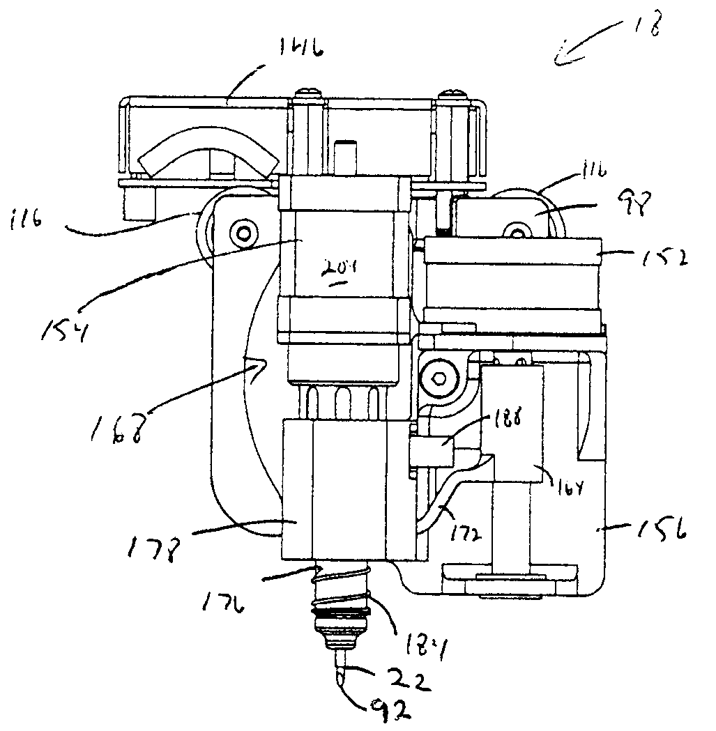
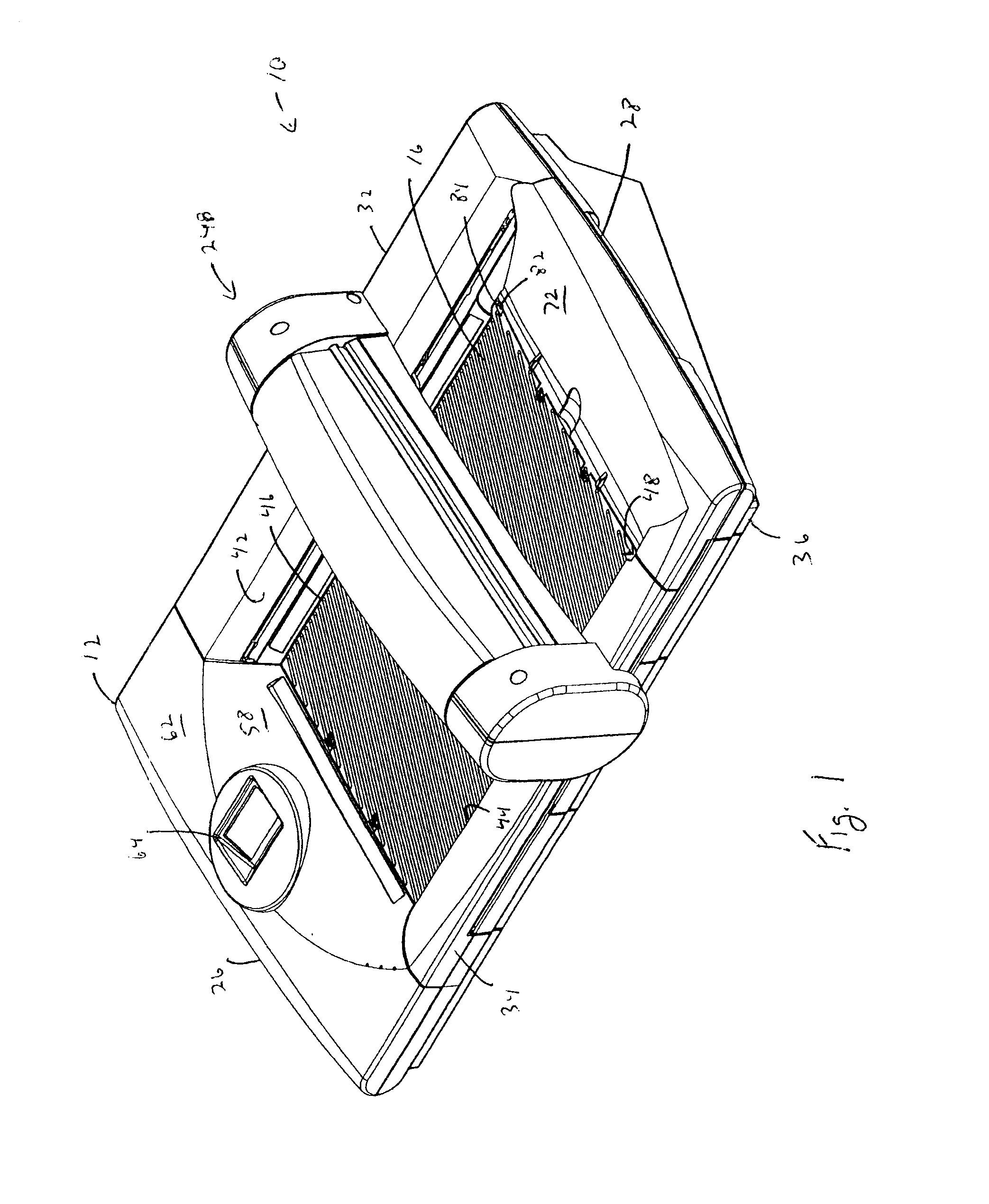
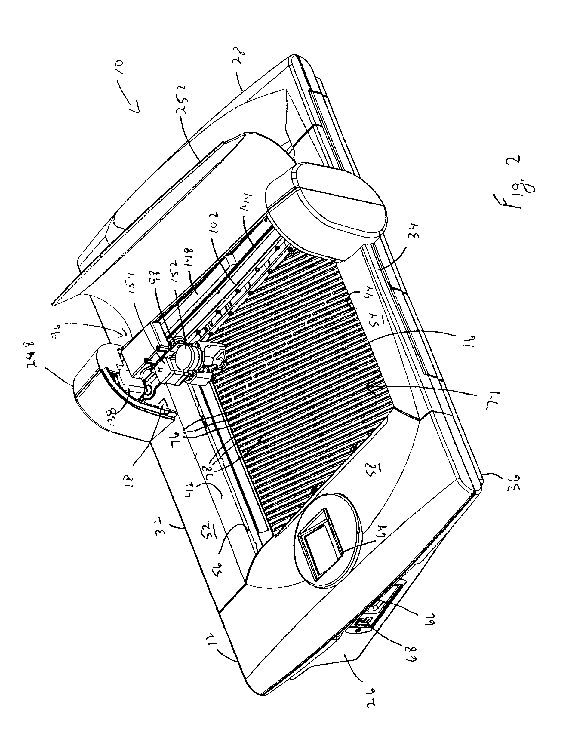
[0018]Referring particularly to FIGS. 1-3, a sheet cutting apparatus 10 employing a preferred embodiment of the present invention includes a housing 12 enclosing a vacuum manifold 14 and surrounding a porous top plate 16 that supports a sheet of material being cut. A cutting head 18 is supported above the top plate 16 for movement in two dimensions over the top plate 16, and thus the sheet material. A cutting blade 22 extendible from the cutting head 18 is engageable with a cutting blade tip sensor 24 adjacent to the top plate 16 to calibrate the length of the cutting blade 22 extending from the cutting head 18.

[0019]The housing 12 is preferably molded plastic having opposing front and rear exterior ends 26, 28 joined by opposing exterior side walls 32, 34 supported by an integral base 36. Interior side walls 42, 44 spaced inwardly from the exterior side walls 32, 34 are adjacent opposing sides 46, 48 of the top plate 16. The interior side walls 42, 44 extend downwardly from side co...


PUM

PropertyMeasurementUnit
Lengthaaaaaaaaaa
Depthaaaaaaaaaa

Abstract

A sheet cutting apparatus that automatically adjusts blade depth for a sheet being cut regardless of the amount of wear on the blade. The apparatus includes a top plate for supporting a sheet being cut. A cutting head is disposed above the top plate and has a cutting blade movable toward the top plate. The cutting blade includes a cutting blade tip which engages a cutting blade tip sensor to indicate a location of the tip relative to the cutting head.

Description

CROSS REFERENCES TO RELATED APPLICATIONS[0001]This application is related to copending U.S. patent application entitled “Cutting Head,” Attorney Docket No. 180825.00057, filed concurrently with the present application.STATEMENT REGARDING FEDERALLY SPONSORED RESEARCH[0002]Not ApplicableTECHNICAL FIELD[0003]The present invention relates to a sheet cutting system, and more particularly to a cutting system having a cutting tip sensor.DESCRIPTION OF THE BACKGROUND ART[0004]There are a number of U.S. patents that disclose cutting systems having a cutting head movably mounted on a gantry system for moving the cutting head in two dimensions, such as U.S. Pat. Nos. 3,967,519, 4,624,169, 4,524,894, 4,793,033, 5,262,617, and 5,275,077. The cutting blades in these prior art cutting systems are subject to wear requiring periodic manual adjustments by a technician to obtain reliable cut output.[0005]Prior art cutting systems are often used to cut sheets of material having different characteristic...

Claims


Application Information

Patent Timeline
IPC IPC(8): B26D3/00
CPCB26D3/085B26F1/3813B26D7/2628B26D5/02Y10T83/0605
Inventor ROACH, WILLIAM A.PARR, PERCY A.CHRYST, CHAD A.
Owner BRADY WORLDWIDE INC
Why Eureka
Try Eureka