Radar apparatus

a radar and target technology, applied in the direction of process and machine control, using reradiation, instruments, etc., can solve the problems of inadequate vehicle control, vehicle control apparatus cannot acquire the target information of pre-preceding vehicles, etc., to prevent erroneous control

Active Publication Date: 2015-10-29
FUJITSU GENERAL LTD
View PDF10 Cites 5 Cited by
  • Summary
  • Abstract
  • Description
  • Claims
  • Application Information

AI Technical Summary

Benefits of technology

[0013]Accordingly, the radar apparatus is capable of determining whether or not the first target is a target present at a position closest to the own lane within the own lane accurately, and is capable of reliably determining whether or not the second target is to be set to an output object with respect to the control apparatus.
[0014]Therefore, it is an object of the invention to provide a technology to detect a pre-preceding vehicle reliably when a preceding vehicle changes the lane in a state in which the preceding vehicle and the pre-preceding vehicle are present while preventing erroneous control due to an accessory portion of the vehicle.

Problems solved by technology

However, if the radar apparatus determines that the pre-preceding vehicle is the target of the accessory portion by the mirror determination process, an output of the target information of the pre-preceding vehicle to the vehicle control apparatus is not performed.
Therefore, the vehicle control apparatus cannot acquire the target information of the pre-preceding vehicle even though the pre-preceding vehicle, which becomes in turn the preceding vehicle is actually present in front of the vehicle.
Consequently, the vehicle control apparatus may determine that no follow-up object is present in front of the vehicle, and perform inadequate control on the vehicle such as accelerating the vehicle until the target information as another follow-up object is acquired from the radar apparatus.

Method used


Image

  • Radar apparatus
  • Radar apparatus
  • Radar apparatus

Examples


first embodiment

1. System Block Diagram

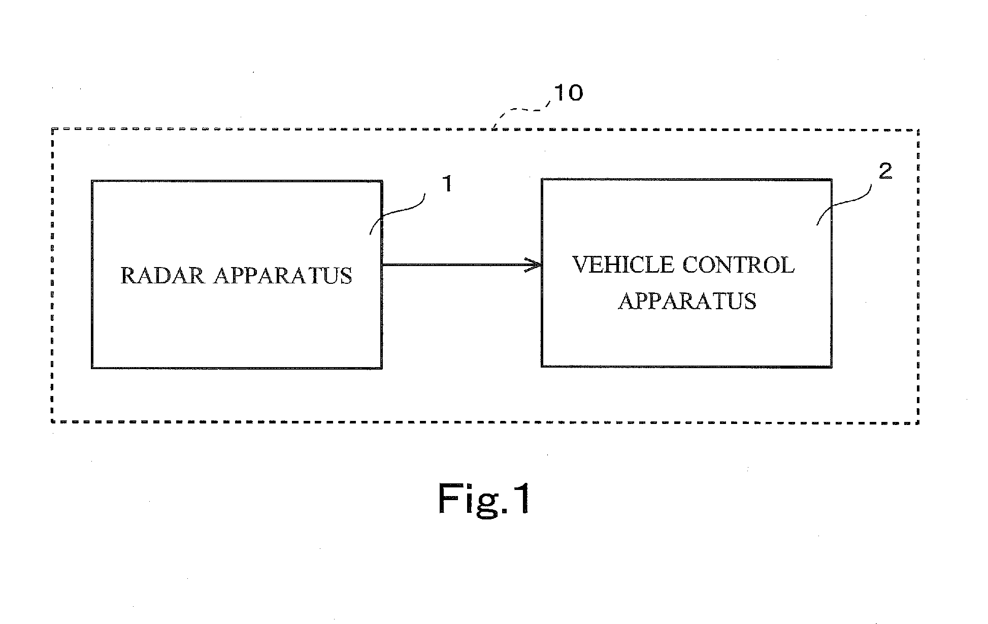
[0031]FIG. 1 is a drawing illustrating a configuration of a vehicle control system 10 of an embodiment. The vehicle control system 10 is mounted on a vehicle (host vehicle). As illustrated in the drawing, the vehicle control system 10 includes a radar apparatus 1 and a vehicle control apparatus 2.

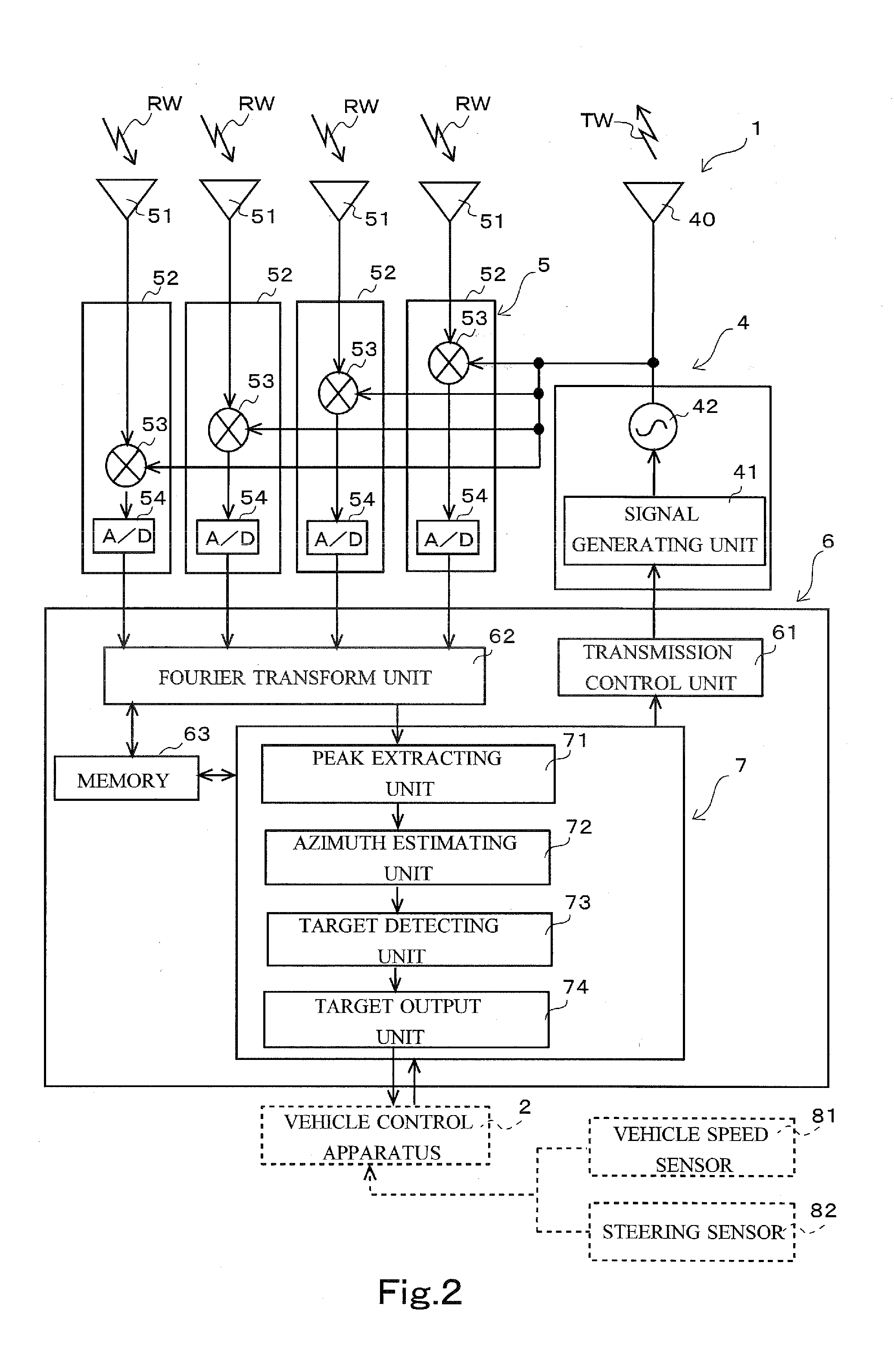
[0032]The radar apparatus 1 of this embodiment detects a target present in the periphery of the vehicle by using an FM-CW (Frequency Modulated Continuous Wave), which is a continuous wave modulated in frequency thereof. The target has target information. The target information includes for example, a distance [m] that a reflected wave reflected from the target travels until being received by a receiving antenna of the radar apparatus 1 (hereinafter, referred to as a “fore-and-aft distance”), a relative speed [m / s] of the target with respect to the vehicle, and a distance [m] of the target in a lateral direction of the vehicle (vehicle width direction) (hereinafter, re...

second embodiment

[0185]Subsequently, a second embodiment will be described. A radar apparatus 1 of the second embodiment includes a vehicle determination process anew added in the output determination process described in the first embodiment. This vehicle determination process is a process in which candidate data which is not included in a determination range DE out of candidate data detected in an own lane OR is determined as data of a main body of a vehicle, not of an accessory portion.

[0186]The configuration and the process of the radar apparatus 1 of the second embodiment is substantially the same as that of the first embodiment. However, the contents of the process in the output determination is partly different as descried above. The different points will be mainly described with reference to FIG. 11 to FIG. 14.

[0187]6-1. Processing of Output Determination

[0188]FIG. 11 is a flowchart for explaining a process of an output determination of the second embodiment. FIG. 11 illustrates a process of...


PUM


Abstract

A radar apparatus is configured to set a first target to be a non-output object with respect to a control apparatus of a host vehicle in a case where the first target (1) has a fore-and-aft distance from the host vehicle that is larger than a fore-and-aft distance from the host vehicle of a second target and (2) has a predetermined dependency to be an accessory portion which belongs to a same vehicle as the second target. The radar apparatus includes a signal processor configured to: determine whether or not the second target is present in an own lane of the host vehicle; determine whether or not the second target is changing a lane; and set the first target to be an output object with respect to the control apparatus of the host vehicle in a case where the second target is changing the lane from the own lane.

Description

BACKGROUND OF THE INVENTION[0001]1. Field of the Invention[0002]The present invention relates to a signal processing for detecting a target.[0003]2. Description of the Background Art[0004]In the related art, a radar apparatus provided on a vehicle detects a target in the periphery of the vehicle, and outputs target information of the target to a vehicle control apparatus. The vehicle control apparatus uses the target information acquired from the radar apparatus and causes the vehicle to follow a preceding vehicle while repeating acceleration and deceleration so as to maintain a distance from the preceding vehicle constant. A vehicle control system functions as a system having the radar apparatus and the vehicle control apparatus and causing the vehicle to follow the preceding vehicle.[0005]However, when an adjacent vehicle in a lane next to an own lane travels on a side closer to the own lane, part other than the vehicle body of the adjacent vehicle (for example, a side mirror) may...

Claims


Application Information

Patent Timeline
Patent Type & Authority Applications(United States)
IPC IPC(8): G01S13/04B60W30/16G01S13/88G01S13/931
CPCG01S13/04B60W30/16G01S13/88G01S7/41G01S13/345G01S13/726G01S13/931G01S2013/9321B60W2420/52B60W30/0956G01S2013/9319G01S2013/93185G01S2013/932G01S2013/93271
Inventor ITOH, JUNISHIMORI, HIROYUKI
Owner FUJITSU GENERAL LTD
Why Eureka
Try Eureka