Method for producing multilayer ceramic substrate

a multi-layer ceramic and substrate technology, applied in the direction of water-setting substance layered product, transportation and packaging, chemistry apparatus and processes, etc., can solve the problems of large-scale cosub>2 /sub>laser irradiation apparatus, substrate breakage, and high cost, so as to achieve accurate and easy production of multi-layer ceramic substrates

Active Publication Date: 2008-06-12
MURATA MFG CO LTD
View PDF9 Cites 15 Cited by
  • Summary
  • Abstract
  • Description
  • Claims
  • Application Information

AI Technical Summary

Benefits of technology

[0009]To overcome the problems described above, preferred embodiments of the present invention provide a source substrate for forming multilayer ceramic substrates and a method for accurately and easily producing a multilayer ceramic substrate.
[0020]In this case, the firing shrinkage of the green ceramic laminate is inhibited by the shrinkage inhibiting layer in the direction perpendicular to the stacking direction (i.e., a main surface direction). The green ceramic laminate shrinks significantly in the thickness direction, thereby easily forming the cavity at a side of the boundary-defining thick-film pattern.
[0025]In this case, the boundary-defining conductive pattern can also function as at least a portion of the internal circuit conductive pattern defining the embedded element. The boundary-defining conductive pattern and the internal circuit conductive pattern can be composed of the same material, thus simplifying the process. Furthermore, the boundary-defining conductive pattern and the internal circuit conductive pattern can be arranged with no space therebetween, thus resulting in a reduction in the size of the multilayer ceramic substrate. Moreover, the embedded element can be electrically connected to the outside with the boundary-defining conductive pattern exposed at edges of the sintered ceramic laminate.
[0030]According to preferred embodiments of the present invention, the sintered laminate is divided by utilizing the cavity formed due to the difference in firing shrinkage characteristics between the green ceramic layers and the green boundary-defining thick-film pattern. Thus, the multilayer ceramic substrate can be produced accurately and easily.
[0031]That is, edges of the sintered ceramic laminate pass through the cavity, thereby preventing misalignment and variations in the shape of the multilayer ceramic substrates. This also prevents separation at an undesirable location, breakage during cutting, or variations among the break edges.
[0032]Furthermore, a thick-film pattern may be simply formed at a desirable location of the green ceramic laminate as well as a conductive pattern. The cavity is formed by firing. Thus, deformation and breakage are not caused by the cavity during the conveyance of the green multilayer ceramic substrate. The sintered ceramic laminate can be easily cut by applying a stress to the cavity. Thus, an expensive, large-scale CO2 laser irradiation apparatus is not required. The application of heat is not required during cutting, thereby preventing the deformation and alteration caused by heat at and in the vicinity of the break edges.

Problems solved by technology

In Japanese Unexamined Utility Model Registration Application Publication No. 4-38071, however, an expensive, large-scale CO2 laser irradiation apparatus is required.
The laser irradiation requires a long time.
During cutting, the substrates may be broken by thermal strain, and deformation and / or alteration due to the heat of the laser may occur in sections of the substrate.
In the method disclosed in Japanese Unexamined Patent Application Publication No. 5-75262, in the press-bonded sheets after the formation of the dividing grooves, failures, such as deformation and breakage, may occur due to the dividing grooves during handling of the press-bonded sheets.
When the heat-treated substrate is bent, the substrate may be broken at undesirable locations other than the grooves, resulting in defective articles.
Although the substrate is separated along the dividing grooves, edges may have irregular shapes, resulting in out-of-specification products.

Method used


Image

  • Method for producing multilayer ceramic substrate
  • Method for producing multilayer ceramic substrate
  • Method for producing multilayer ceramic substrate

Examples


first preferred embodiment

[0042]A method for producing a multilayer ceramic substrate according to a first preferred embodiment will be described below with reference to FIGS. 1A to 4.

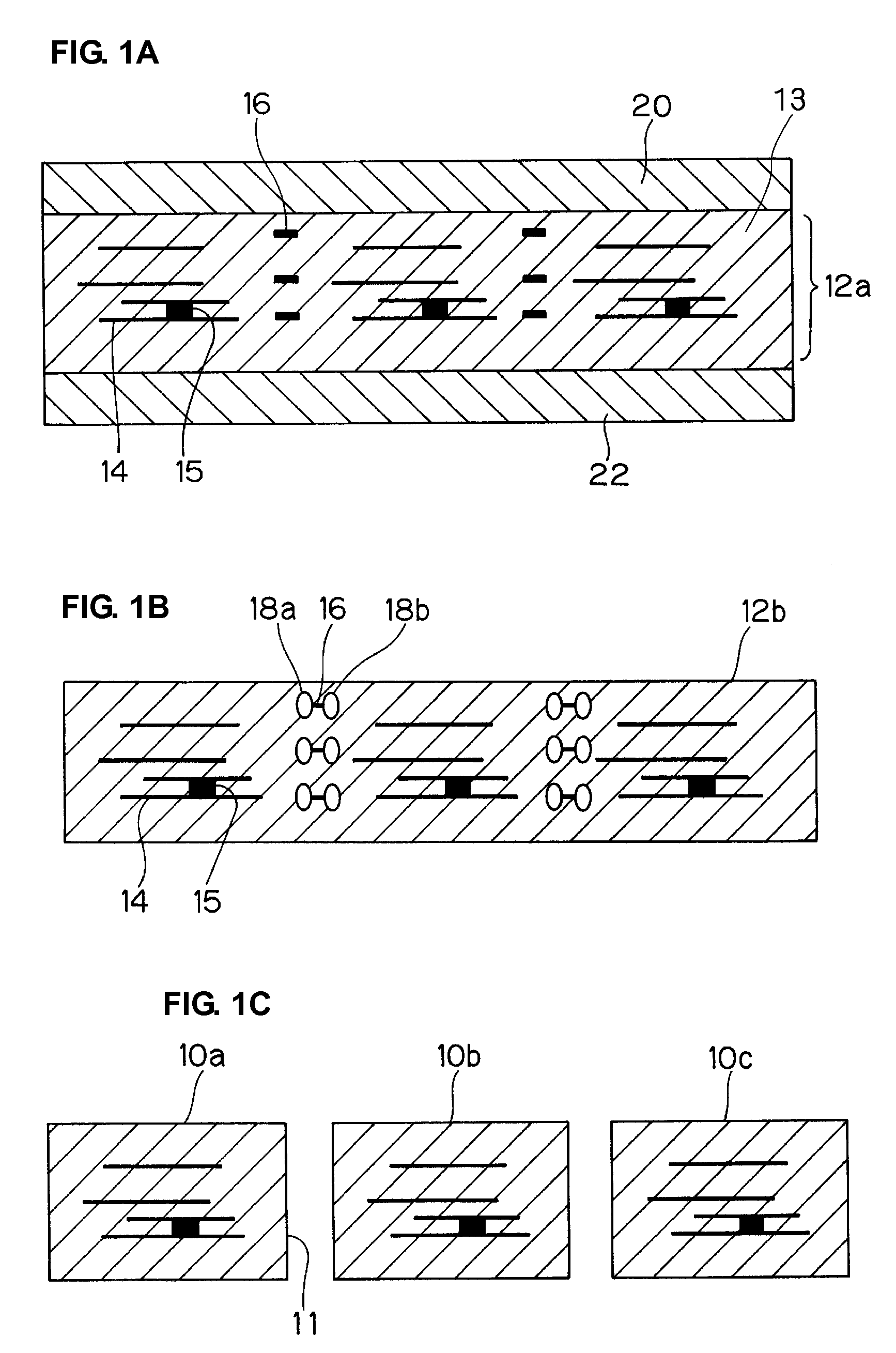
[0043]A brief outline of the method for producing a multilayer ceramic substrate will be described below with reference to FIGS. 1A to 1C which are cross-sectional views.

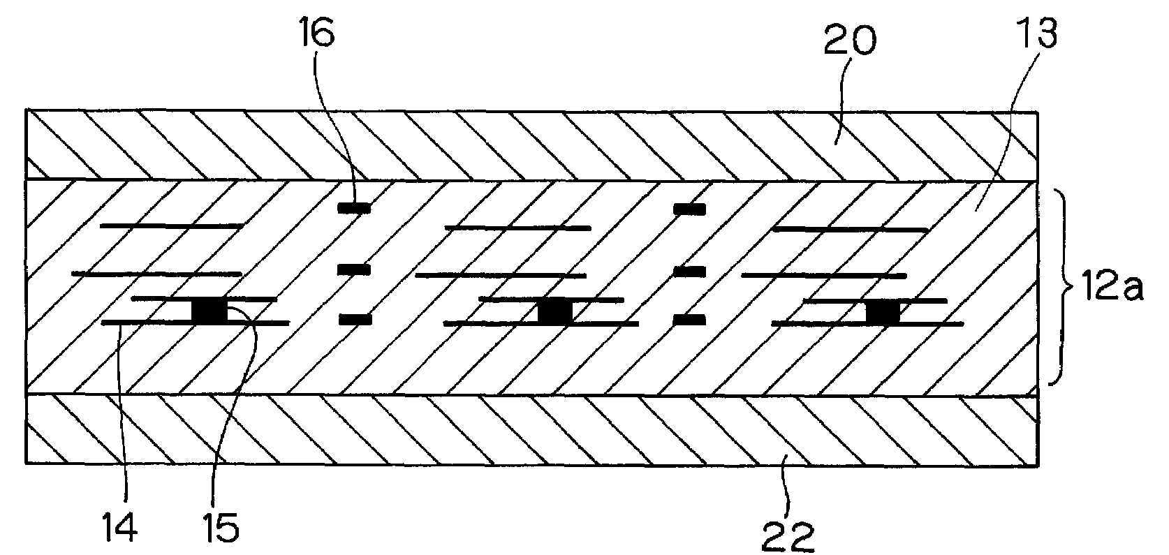
[0044]As shown in FIG. 1A, shrinkage inhibiting green sheets 20 and 22 in close contact with both surfaces of a green ceramic laminate 12a including portions to be formed into a plurality of multilayer ceramic substrates are fired.

[0045]The green ceramic laminate 12a includes in-plane conductive patterns 14 to be formed into internal electrodes, internal leads, embedded elements, and other circuit components in the multilayer ceramic substrates, the in-plane conductive patterns 14 being arranged between a plurality of stacked ceramic green sheets 13; and boundary-defining conductive patterns 16 arranged along boundaries between the multilayer ceramic substrates...

second preferred embodiment

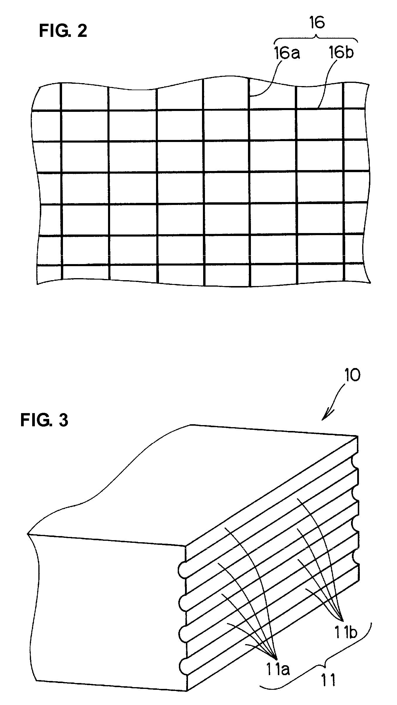
[0082]The ceramic laminate is separated at an edge through one of the cavities formed at both edges of each boundary-defining conductive pattern. To form the edge more accurately, as shown in FIG. 5, the locations and widths of the boundary-defining conductive patterns 16p, 16q, 16r, and 16s may be changed such that sides 17p, 17q, 17r, and 17s of individual boundary-defining conductive patterns 16p, 16q, 16r, and 16s are aligned along the boundaries of the multilayer ceramic substrates. Thereby, the ceramic laminate after firing can be separated at edge 11s passing through the cavities 18 formed at the sides 17p, 17q, 17r, and 17s aligned in the stacking direction of the boundary-defining conductive patterns 16p, 16q, 16r, and 16s.

[0083]The boundary-defining conductive patterns may also be arranged on both sides of the break edge. Alternatively, the boundary-defining conductive patterns may overlap the in-plane conductive patterns.

third preferred embodiment

[0084]As shown in FIG. 6, boundary-defining conductive pattern segments 16s and 16t may be discontinuously formed.


PUM

PropertyMeasurementUnit
softening pointaaaaaaaaaa
viscosityaaaaaaaaaa
particle sizeaaaaaaaaaa

Abstract

In a method for producing a multilayer ceramic substrate, a green ceramic laminate includes green conductive patterns arranged on a plurality of ceramic green sheets and portions to be formed into a plurality of multilayer ceramic substrates. Boundary-defining conductive patterns are arranged on the ceramic green sheets and along boundaries of the multilayer ceramic substrates. The boundary-defining conductive patterns have firing shrinkage characteristics that are different from those of the ceramic green sheets. During firing of the green ceramic laminate, cavities adjacent to edges of the boundary-defining conductive patterns are formed. A sintered ceramic laminate is divided at edges passing through the cavities.

Description

BACKGROUND OF THE INVENTION[0001]1. Field of the Invention[0002]The present invention relates to a method for producing a multilayer ceramic substrate. In particular, the present invention relates to a method for producing a multilayer ceramic substrate including a plurality of stacked ceramic layers.[0003]2. Description of the Related Art[0004]Multilayer ceramic substrates including a plurality of stacked ceramic layers can be efficiently produced by simultaneously firing a source substrate including a plurality of multilayer ceramic substrates and cutting the source substrate into individual multilayer ceramic substrates after firing.[0005]For example, Japanese Unexamined Utility Model Registration Application Publication No. 4-38071 discloses that ceramic green sheets having dividing lines are transferred and laminated to form a laminate, dividing grooves are formed by, for example, irradiating the dividing lines with a CO2 laser after the laminate is subjected to heat treatment,...

Claims


Application Information

Patent Timeline
Patent Type & Authority Applications(United States)
IPC IPC(8): C03B29/00
CPCH01L21/4807H05K1/0272H05K1/0306H05K3/0052Y10T428/166H05K3/4629H05K2201/0909H05K2201/09163H05K2201/09781H05K3/4614H05K3/46
Inventor KAWAMURA, AKIYOSHITSUKIZAWA, TAKAYUKIIKEDA, TETSUYA
Owner MURATA MFG CO LTD
Why Eureka
Try Eureka