Apparatus and method for converting insulated panels

a technology of insulated panels and duct pieces, applied in the direction of work holders, manufacturing tools, metal-working machine components, etc., to achieve the effect of easy and accurate separation of duct pieces

Active Publication Date: 2014-05-27
LANCIAUX FRAN
View PDF14 Cites 4 Cited by
  • Summary
  • Abstract
  • Description
  • Claims
  • Application Information

AI Technical Summary

Benefits of technology

[0009]The invention is also concerned with a workpiece hold down system for a three axis cutting machine. The hold down system comprises a work table having an upper surface, a plurality of pegs for supporting a work piece in spaced relationship with the work table upper surface so that a plenum is defined between the work table upper surface and a major surface of the work piece. Vacuum ports connect the plenum and a vacuum system connected to withdraw a sufficient quantity of air from the plenum to increase the frictional engagement between the pegs and the work piece so that the work piece is held fast on the pegs, even while the cutting machine removes portions of the work piece. Preferably, the vacuum system is of the centrifugal blower type.
[0011]Accordingly, it is an object of this invention to provide a system for accurately and easily producing such parts.
[0013]It is yet another object of the invention to provide a system where a hand tool can be used on site to easily and accurately separate the duct pieces, previously cut off site, from one another and from scrap in the workpiece for assembly and installation on site.

Problems solved by technology

However, foam board is remarkably light, with excellent thermal insulating properties, and often sufficiently rigid itself for duct applications although long unsupported spans, large cross-sectional areas, or significant differential pressures between interior and exterior may require reinforcement or additional support.

Method used


Image

  • Apparatus and method for converting insulated panels
  • Apparatus and method for converting insulated panels
  • Apparatus and method for converting insulated panels

Examples


Embodiment Construction

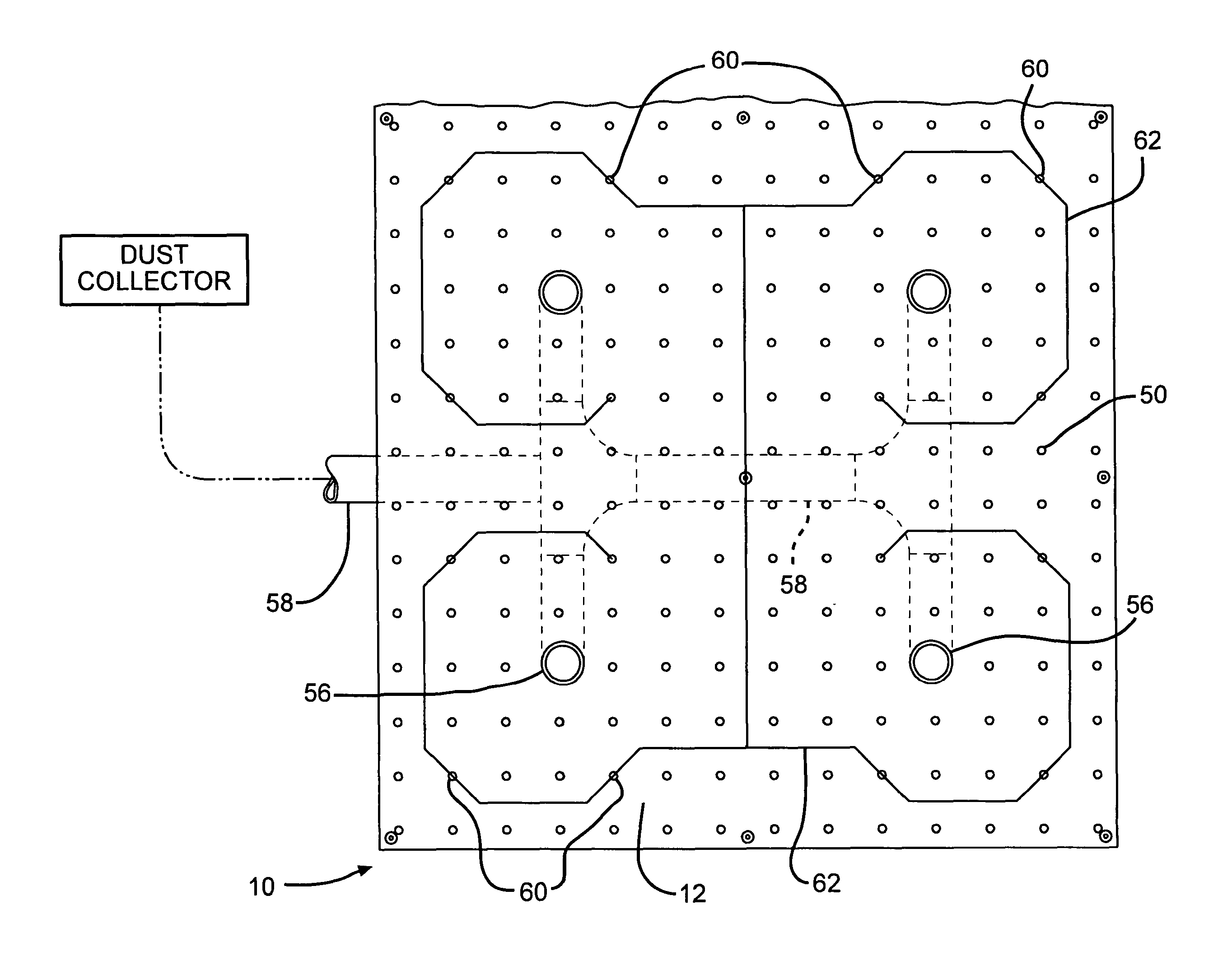
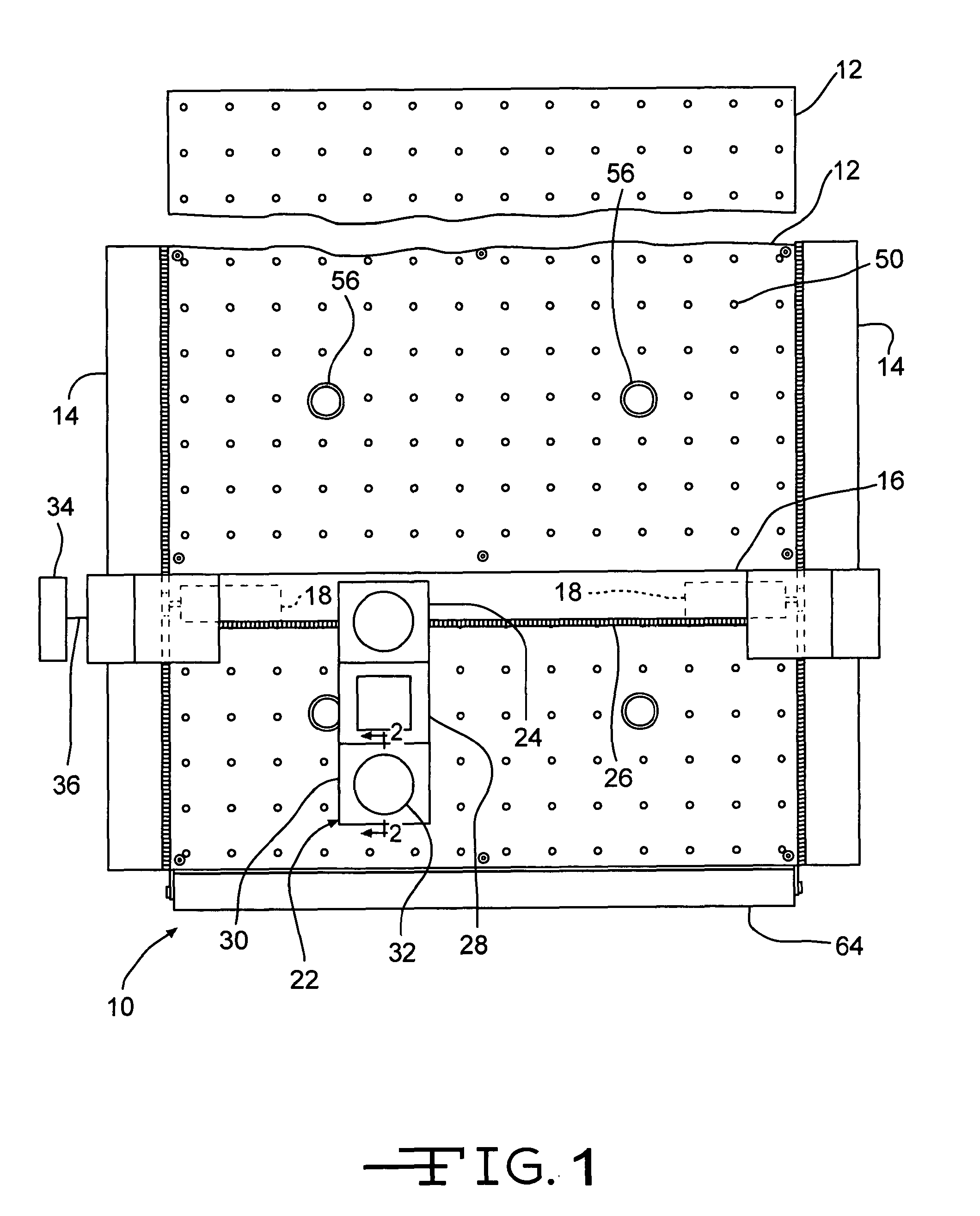
[0028]Referring now in more detail to the drawing figures, FIG. 1 shows a three axis (X, Y and Z) cutting machine indicated generally at 10 and including a work table 12 supported on a frame, side members of which are indicated at 14. A gantry 16 is supported relative to the table 12 for movement in the “Y” direction (up and down in FIG. 1) under the action of tandem stepper motors 18 mounted on the gantry 16 for movement therewith relative to the frame members 14 and, specifically, relative to tracks 20 supported thereon. It will certainly be appreciated that other Y axis actuators or actuator systems, now known or hereinafter developed, may be incorporated in the apparatus 10 to effect movement of the gantry 16 in the Y direction.

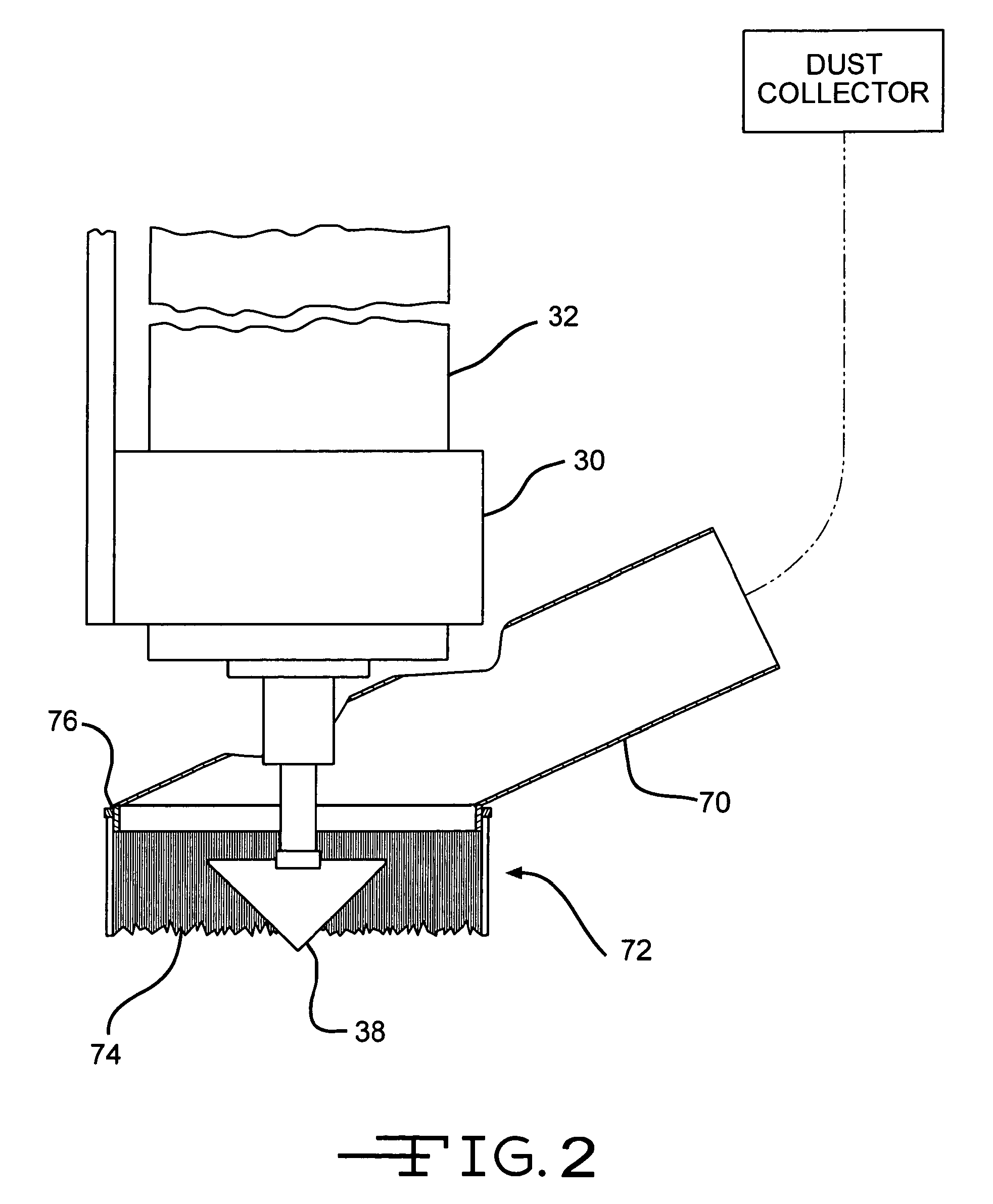
[0029]Mounted on the gantry 16, for movement therewith, is a tool carriage indicated generally at 22 and comprising an X axis actuator 24 for effecting movement of the carriage 22 in the “X” direction (left and right in FIG. 1) relative to the gantry 16 a...


PUM

PropertyMeasurementUnit
angleaaaaaaaaaa
angleaaaaaaaaaa
thicknessesaaaaaaaaaa

Abstract

A method for producing a duct from a planar board having two opposed substantially parallel edges with metal foil facings on opposed major surfaces of the board is disclosed. The method comprises making planar cuts through one of the metal foil facings and at least most of the planar board there below to produce a blank with 3 parallel “V shaped grooves which are parallel to angled edges of the blank. A duct is formed by folding the blank so that the “V” shaped grooves form three of the edges of the duct, and the angled edges form the fourth of the edges.

Description

BACKGROUND OF THE INVENTION[0001]1. Field of the Invention[0002]The present invention relates to methods and apparatus for converting flat boards for use in constructing ducts and duct fittings. The methods and the apparatus are particularly well suited for use with boards that are rigid or semi-rigid and are produced specifically for use in fabricating insulated ducts for heating, ventilating and air conditioning applications.[0003]2. Description of the Prior Art[0004]Boards that are commercially available today are being produced for use in forming thermally insulating ducts such as are employed for heating, ventilation and air conditioning. In one case, these boards consist of a rigid foamed plastics material, namely, a closed cell expanded phenolic foam in the form of a planar board having a metallic foil such as aluminum bonded to each major surface. One example of such a board is sold under the trademark KOOLDUCT®. The apparatus and methods of the present invention are especia...

Claims


Application Information

Patent Timeline
Patent Type & Authority Patents(United States)
IPC IPC(8): B25B11/00B23Q1/00
CPCB29L2009/003B23Q11/0046B26D1/10B25B11/005B26D3/065B29C53/063Y10T83/207Y10T83/7587Y10T83/0524
Inventor LANCIAUX, FRAN
Owner LANCIAUX FRAN
Why Eureka
Try Eureka