
Radial Shaft Seal

a radial shaft and sealing element technology, applied in the field of radial shaft seals, can solve the problems of vulcanizing the sealing element, requiring a long processing time, and unable to meet the requirements of the sealing element, and achieve the effect of simple and inexpensive way

Inactive Publication Date: 2008-06-12
KACO
View PDF7 Cites 8 Cited by
  • Summary
  • Abstract
  • Description
  • Claims
  • Application Information

AI Technical Summary

Benefits of technology

[0003]It is an object of the present invention to configure a seal of the aforementioned kind such that it can be produced in a shorter amount of time and at reduced manufacturing costs with at least the same quality.
[0006]As a result of the configuration according to the invention, the sealing element is separately produced as a part independent from the support body. The sealing element is not vulcanized to the support body but is produced as a separate shaped part. Since the vulcanization step is no longer required, the previously required binder is no longer needed. The sealing element requires less material because the cone gate injection step is no longer required because a direct injection molding process is possible and because the cross-section of the sealing element according to the invention is significantly thinner in comparison to the prior art shaft seal designs. By means of the adhesive connection the sealing element can be attached simply and reliably to the support body in a short period of time. Rejects of support bodies are prevented because of the adhesive connection. Moreover, the step of cutting off the sealing edge of the sealing element is no longer needed.
[0008]In the seal according to the second embodiment, the static and the dynamic seal parts are components of the sealing element. In this way, the seal can be produced in a simple and inexpensive way.

Problems solved by technology

The manufacture of such a radial shaft seal is complex and requires a relatively long processing time.
As a result of this thick cross-section, a long processing time is required in order to vulcanize the sealing element.
When errors are made during the injection molding process, not only the sealing element but also the expensive metallic support body turn into rejects.

Method used


Image

  • Radial Shaft Seal
  • Radial Shaft Seal
  • Radial Shaft Seal

Examples


Embodiment Construction

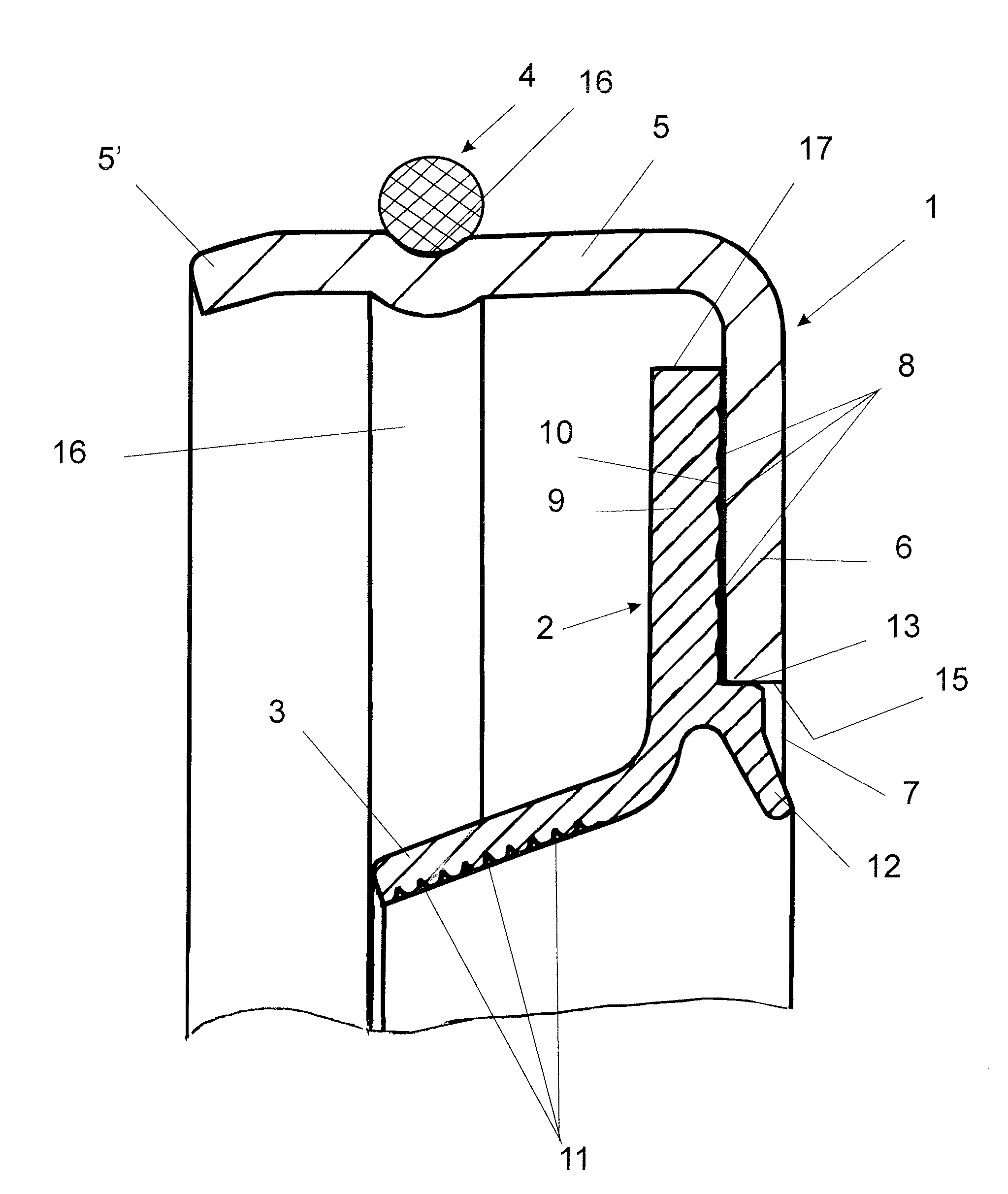
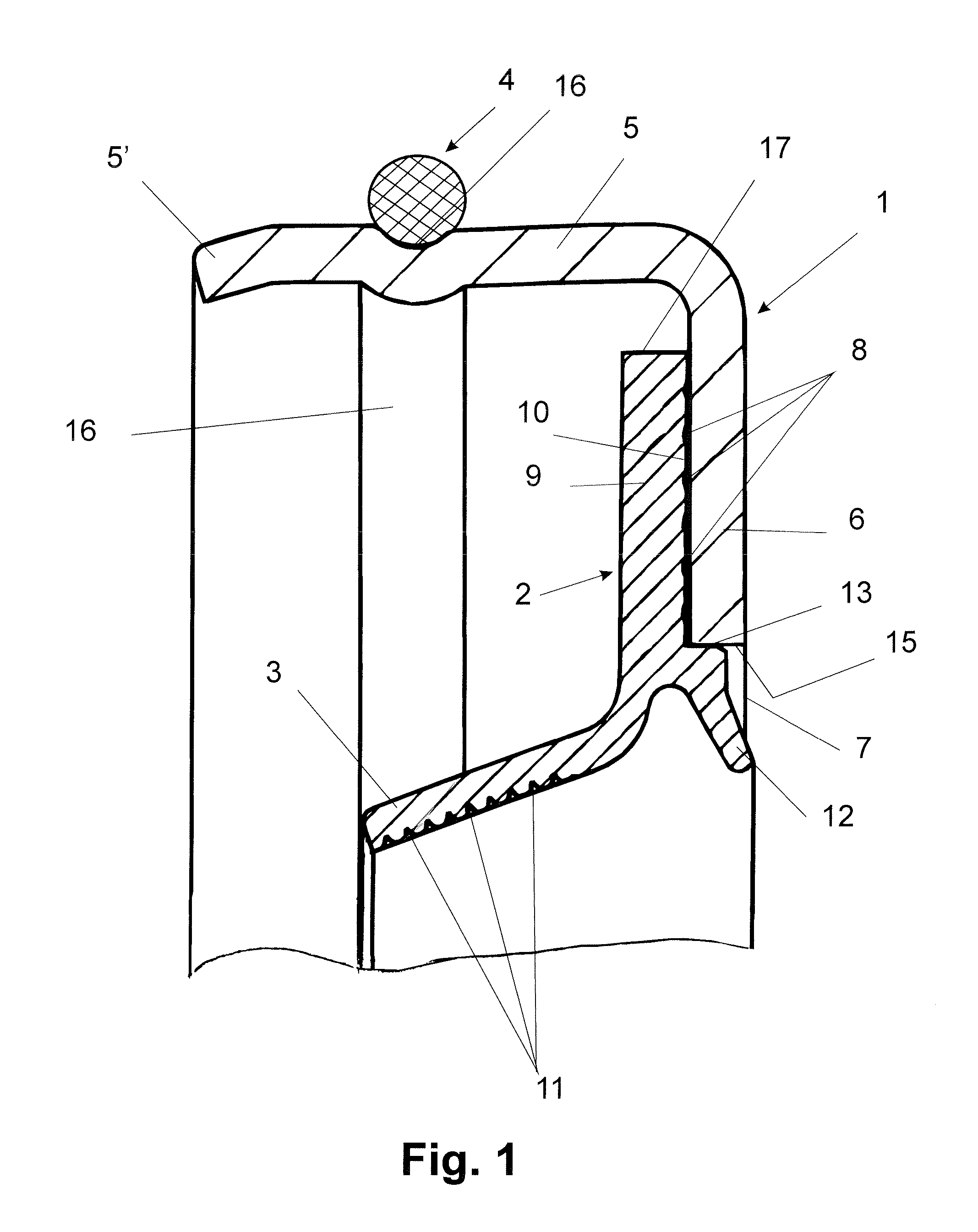
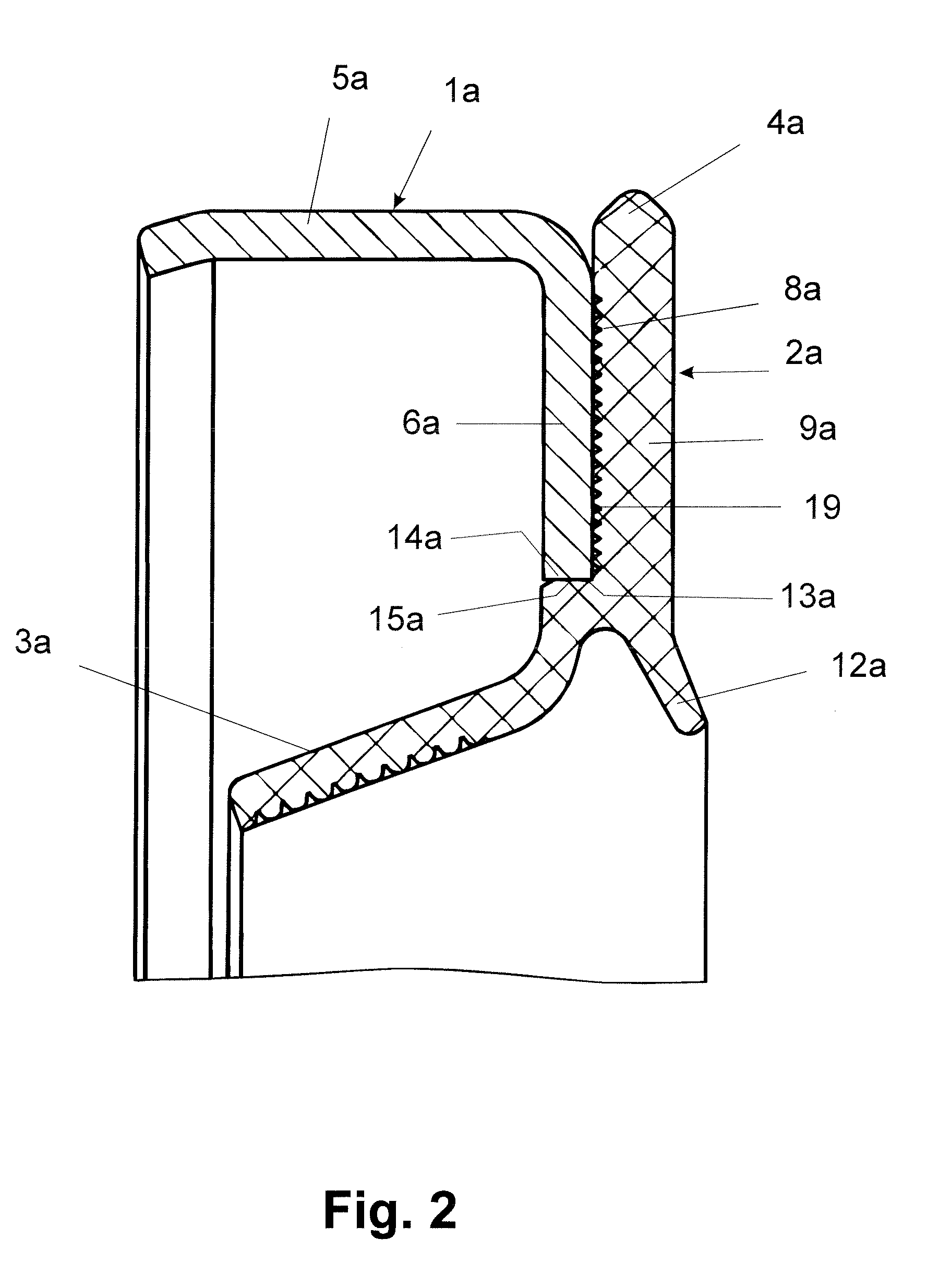
[0013]The radial shaft seals illustrated in FIGS. 1 to 4 serve generally for sealing rotating shafts and for sealing spaces with pressure differences of various degrees.

[0014]The seal according to FIG. 1 is comprised of a support body 1, a sealing element 2 having a dynamic seal part 3 and a static seal part 4. The support body 1 is cup-shaped and made of metal, such as conventional steel, carbon steel, galvanized steel, stainless steel, or is made of hard plastic material. Its essentially cylindrical wall 5 passes into a bottom 6 extending radially relative to the axis of the seal. The bottom 6 has a central opening 7 through which a shaft (not illustrated) projects when the seal is mounted. The free end 5′ of the wall 5 is slightly inwardly bent and forms in this way an insertion aid for mounting the seal. Approximately at half the axial length, the wall 5 has at the exterior side a receptacle in the form of a circumferential groove 16 in which the static seal part 4 is arranged. ...


PUM


Abstract

A radial shaft seal has a support body and at least one sealing element that is a part produced separate from the support body and is connected to the support body by an adhesive connection. A static seal part that is a part separate from the sealing element and is arranged on a wall of the support body is provided. Alternatively, the sealing element comprises an integral static seal part and the static seal part is formed by a radially projecting edge of the holding part of the sealing element that projects radially past the wall of the support body.

Description

BACKGROUND OF THE INVENTION[0001]The invention relates to a seal, in particular, a radial shaft seal, comprising a support body and at least one sealing element.[0002]For sealing rotating shafts and for sealing spaces in which pressure differences exist, radial shaft seals are used. They are comprised in general of a metallic support body, an elastomer sealing element, and a coil tension spring. When producing such radial shaft seals, first the support body is coated with a binder. Subsequently, the support body is placed into a mold into which the elastomer mixture for the sealing element is injected from the center uniformly onto all sides by means of cone gate. In order to provide a permanent connection between the support body and the sealing element, the support body is molded into the elastomer material of the sealing element in such a way that the support body is partially embedded. After injection molding, the cone gate is cut off in the area of a sealing edge. Subsequently,...

Claims


Application Information

Patent Timeline
Patent Type & Authority Applications(United States)
IPC IPC(8): F16J15/16
CPCF16J15/3228F16J15/3276F16J15/3252
Inventor UHRNER, KLAUS-JURGENBLEIER, ROLAND
Owner KACO
Learn More