Miniaturized Piezoelectric Based Vibrational Energy Harvester

a piezoelectric and vibrational energy technology, applied in piezoelectric/electrostrictive transducers, generators/motors, transportation and packaging, etc., can solve the problems of battery depletion quite quickly, inconvenient tire users, present disposal concerns, etc., to achieve double the amount of collected vibrational energy and energy harvesting efficiently

Active Publication Date: 2008-06-12
MICHELIN RECH & TECH SA
View PDF20 Cites 117 Cited by
  • Summary
  • Abstract
  • Description
  • Claims
  • Application Information

AI Technical Summary

Benefits of technology

[0022]In another exemplary embodiment of the present subject matter, a piezoelectric based vibrational energy harvester is formed by bonding a plurality of networked unimorphs on each side of a shared proof mass. This configuration provides more stability for the proof mass and, at the same time, doubles the amount of collecte

Problems solved by technology

In many sensor applications, there is a need for power to operate associated electrical components yet it is often inconvenient, due to maintenance issues, or impossible due to space and mass limitations, to provide this power by conventional means such as batteries or combustion processes.
A typical solution for powering tire electronics systems corresponds to the use of a non-rechargeable battery, which inherently provides an inconvenience to the tire user since proper electronics system operation is dependent on periodic battery replacement.
Conventional batteries also often contain heavy metals that are not environmentally friendly and which present

Method used


Image

  • Miniaturized Piezoelectric Based Vibrational Energy Harvester
  • Miniaturized Piezoelectric Based Vibrational Energy Harvester
  • Miniaturized Piezoelectric Based Vibrational Energy Harvester

Examples


second embodiment

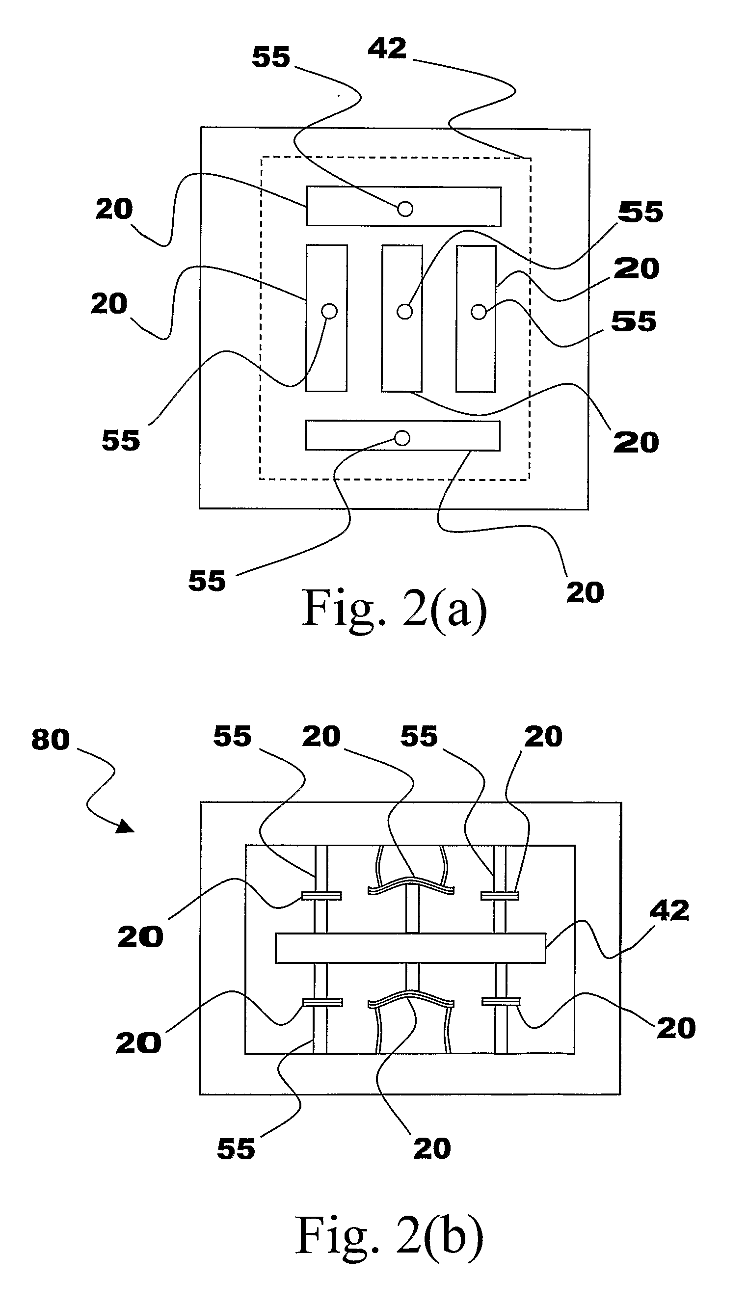
[0058]FIG. 2(a) is a plan view and FIG. 2(b) is a side elevation of a power harvester in accordance with the present subject matter wherein a plurality of networked piezoelectric unimorphs 20 are coupled to a common proof mass 42 by way of support elements 55. Such a networked configuration of a plurality of unimorphs provides not only a significantly higher energy harvesting capability but also improved mechanical stability of the proof mass 42 and greater system design flexibility.

[0059]The embodiment of the present subject matter illustrated in FIG. 2(b) represents a double acting system similar to the embodiment of FIG. 1(d). Another important aspect of the FIG. 2(b) embodiment, however, is that the two sets of unimorphs are positioned on either side of the proof mass 42 in such a manner that the unimorphs are placed into a balanced opposition, that is with nearly equally forces, when the proof mass 42 is at the midpoint of its travel. As with the embodiment of the present techn...


PUM

PropertyMeasurementUnit
Forceaaaaaaaaaa
Poweraaaaaaaaaa
Massaaaaaaaaaa

Abstract

The present subject matter discloses apparatus and methodologies for fabricating apparatus for harvesting power from environmentally induced vibrations. Piezoelectric devices and structures (1600) are disclosed that employ constant force spring or flexure arrangements (1512) in balanced opposition configurations (1510, 1534) to enhance the power harvesting capabilities of the piezoelectric devices (1600). Power harvesting devices and systems in accordance with the subject technology may concurrently operate as sensors in motion sensitive applications thus providing self-powered monitoring capabilities.

Description

PRIORITY CLAIM[0001]This application is a Continuation-In-Part of previously filed PCT Patent Application entitled “A MINIATURIZED PIEZOELECTRIC BASED VIBRATIONAL ENERGY HARVESTER,” assigned PCT / US 04 / 34701, filed on Oct. 21, 2004, which is incorporated herein by reference for all purposes.FIELD OF THE INVENTION[0002]The present invention generally concerns a compact, miniaturized apparatus and corresponding methodology for harvesting energy generated by a piezoelectric structure exposed to mechanical energy and vibration of host structures as well as methodologies for making piezoelectric energy harvesting apparatus. Host structures may correspond to virtually any physical apparatus but the present technology is particularly well suited for integration with sensor applications.BACKGROUND OF THE INVENTION[0003]In many sensor applications, there is a need for power to operate associated electrical components yet it is often inconvenient, due to maintenance issues, or impossible due t...

Claims


Application Information

Patent Timeline
IPC IPC(8): H02N2/18H01L41/113H01L41/22
CPCB60C23/041B60C23/0411Y10T29/42H01L41/332H02N2/186H10N30/304H10N30/03
Inventor THIESEN, JACK
Owner MICHELIN RECH & TECH SA
Why Eureka
Try Eureka