
Method and apparatus for stopping power supply in RFID system

a radio frequency identification and power supply technology, applied in the direction of power management, instruments, high-level techniques, etc., can solve the problems of limited recognition information of conventional passive rfid tags, limited etc., to increase the battery life of active and semi-active tags , the effect of reducing current consumption

Inactive Publication Date: 2008-06-12
ELECTRONICS & TELECOMM RES INST
View PDF8 Cites 23 Cited by
  • Summary
  • Abstract
  • Description
  • Claims
  • Application Information

AI Technical Summary

Benefits of technology

[0012]The present invention provides a method and apparatus for reducing current consumption and increasing a battery lifespan of a battery-powered high radio frequency identification (RFID) tag in a stand-by mode.

Problems solved by technology

In more detail, the recognition distance of the conventional passive RFID tag is limited to about 5 m, and the recognition information on the conventional passive RFID tag is unreliable if the conventional passive RFID tag is attached to a metal object.
Thus, active and semi-active tags are battery-powered, and thus, the active and semi-active tags have a longer recognition distance than the conventional passive RFID tags and can be applied to more applications than passive tags, however, the active and semi-active tags suffer from a limited battery lifespan.

Method used


Image

  • Method and apparatus for stopping power supply in RFID system
  • Method and apparatus for stopping power supply in RFID system
  • Method and apparatus for stopping power supply in RFID system

Examples


Embodiment Construction

[0020]The present invention will now be described more fully with reference to the accompanying drawings, in which exemplary embodiments of the invention are shown.

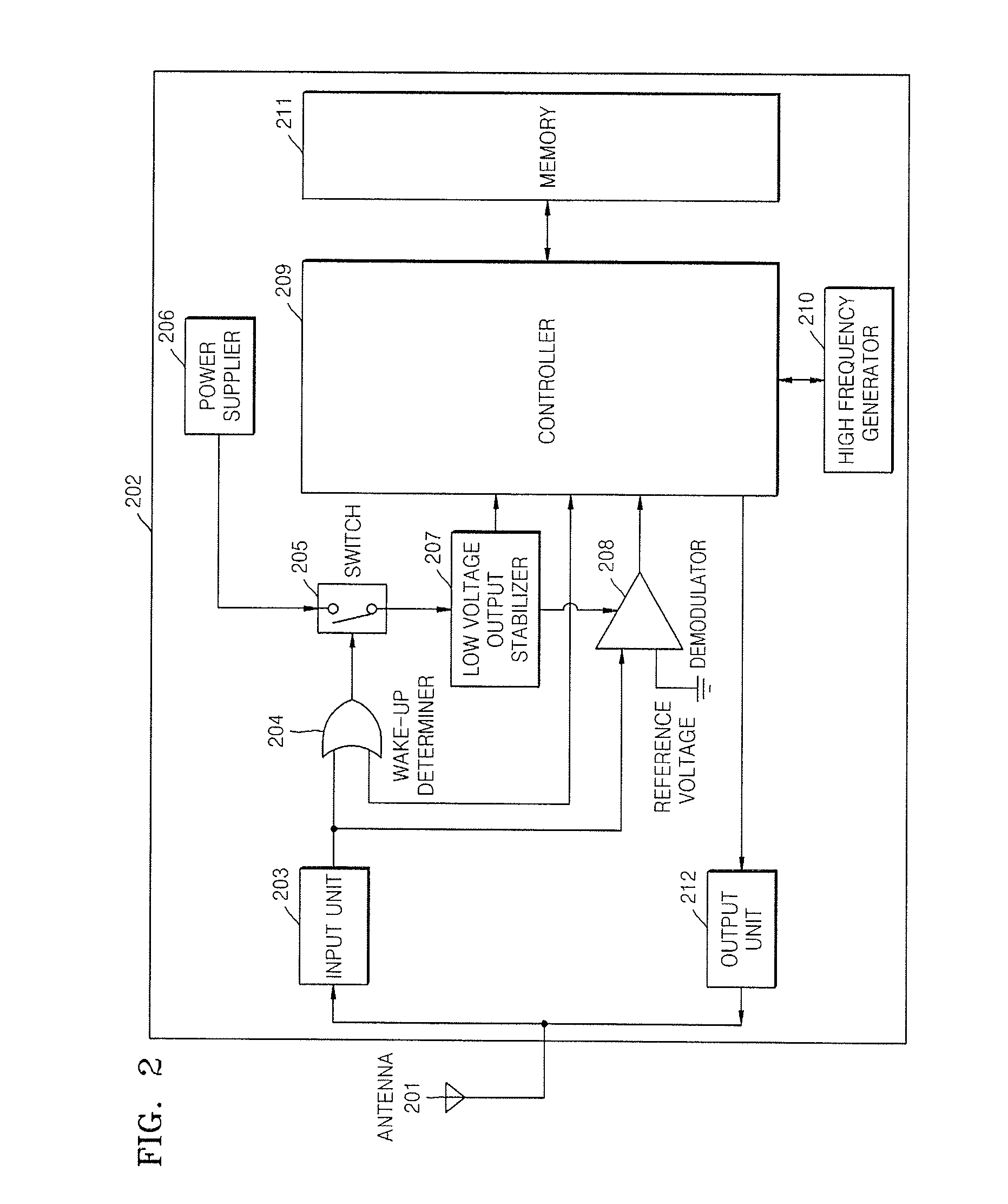
[0021]FIG. 2 is a block diagram of a battery-powered high radio frequency identification (RFID) tag including an apparatus for stopping power supply according to an embodiment of the present invention. Referring to FIG. 2, the battery-powered high RFID tag of the present invention includes an antenna 201 and a tag system 202. An input unit 203 of the tag system 202 receives a signal from a RFID reader through the antenna 201.

[0022]The signal input into the input unit 203 includes a continuous wave signal and a base band signal including a command of the RFID reader.

[0023]The input unit 203 rectifies and boosts the continuous wave signal received through the antenna 201, outputs a direct-current (DC) voltage signal, and transmits the DC voltage signal to a switch 205 through a wake-up determiner 204.

[0024]The wake-up deter...


PUM


Abstract

Provided are a method and apparatus for stopping power supply to a radio frequency identification (RFID) system. The apparatus includes: a power supplier supplying power to a high RFID tag; an input unit rectifying and boosting an input predetermined frequency band signal and outputting a direct-current (DC) voltage signal; a wake-up determiner comparing a voltage of the DC voltage signal output from the input unit with a predetermined reference voltage and outputting a HIGH signal or a LOW signal; and a switch stopping power supply to the high RFID tag if the wake-up determiner outputs the LOW signal.

Description

CROSS-REFERENCE TO RELATED PATENT APPLICATION[0001]This application claims the benefit of Korean Patent Application No. 10-2006-0124765, filed on Dec. 8, 2006, in the Korean Intellectual Property Office, the disclosure of which is incorporated herein in its entirety by reference.BACKGROUND OF THE INVENTION[0002]1. Field of the Invention[0003]The present invention relates to a method and apparatus for stopping power supply in a radio frequency identification (RFID) system, and more particularly, to a method and apparatus for determining whether a battery included in a RFID tag is powered using a continuous wave signal and a command signal of a RFID reader.[0004]The present invention was supported by the IT R&D program of Ministry of Information and Communication Republic of Korea (MIC). [2005-S-106-02, Development of Sensor Tag and Sensor Node Technologies for RFID / USN][0005]2. Description of the Related Art[0006]Conventionally, in a radio frequency identification (RFID) technique, t...

Claims


Application Information

Patent Timeline
IPC IPC(8): H04Q5/22
CPCG06K19/0701H04W52/0245G06K19/0723Y02D30/70G05F1/66G06K19/07H02H7/20
Inventor JUNG, JAE-YOUNGSON, HAE WONYEO, JUN HOSEO, JONG HYUNCHOI, SU NACHOI, GIL YOUNGPYO, CHEOL SIG
Owner ELECTRONICS & TELECOMM RES INST
Learn More