Optical Module

a technology of optical modules and optical elements, applied in the field of optical modules, can solve the problems and achieve the effect of easy resin hardening irregularities

Active Publication Date: 2008-06-12
LUMENTUM JAPAN INC
View PDF8 Cites 4 Cited by
  • Summary
  • Abstract
  • Description
  • Claims
  • Application Information

AI Technical Summary

Benefits of technology

[0007]However, in this method, there is a problem that the hardening irregularity of resin is easily caused due to irregularity easily caused in the irradiation intensity distribution of ultraviolet rays to resin. The hardening irregularity often causes an optical displacement such as an optical axis displacement between the light receiving device and the receptacle, the displacement of a focal position in the axial direction, and the like.
[0008]An objective of the present invention is to provide an optical module, which is hard to cause a hardening irregularity at the adhering period, and consequently, is hard to cause an optical displacement.

Problems solved by technology

However, in this method, there is a problem that the hardening irregularity of resin is easily caused due to irregularity easily caused in the irradiation intensity distribution of ultraviolet rays to resin.

Method used


Image

  • Optical Module
  • Optical Module
  • Optical Module

Examples


Embodiment Construction

[0023]Hereinafter, embodiments will be described with reference to the drawings.

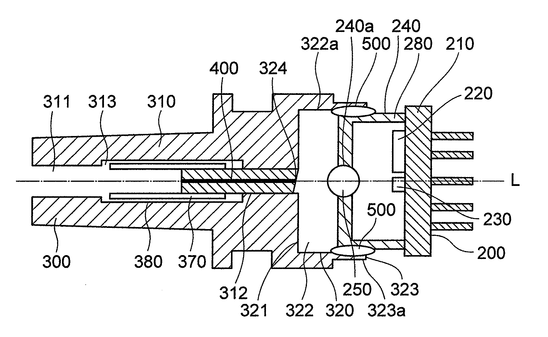
[0024]An optical module according to a first embodiment in FIG. 1 comprises a light receiving device 200 and a receptacle 300.

[0025]The light receiving device 200 comprises a light receiving element 230, an IC 220 amplifying an electrical signal, a metal base 210 mounted with those components, and a cap 280 attached with lens. The cap 280 attached with lens comprises a collecting lens 250 to collect a light toward the light receiving element 230, and a lens holder 240. The lens holder 240 is provided with a penetration hole 240a coaxially with an optical axis L to dispose the collecting lens 250. The collecting lens 250 is fixed to the penetration hole 240a of the lens holder 240 by a low melting point glass, for hermetic sealing. This cap 280 attached with lens is mounted on the metal base 210 to be fixed. Specifically, the cap 280 attached with lens is, for example, resistance-welded to the metal base ...


PUM


Abstract

The optical module comprises a device mounted with a photoelectric element and a receptacle to optically connect this device and an optical fiber is provided. The receptacle comprises a device holder at its one end, allows the device holder to be fitted to the top end side of the device, and fixed and held through the interposition of the ultraviolet curing resin. The device holder comprises a window area relatively large in an amount of ultraviolet transmission dispersedly arranged on the entire periphery of the fitted portion with the device.

Description

BACKGROUND OF THE INVENTION[0001](1) Field of the Invention[0002]The present invention relates to a technique for connecting an optical element and an optical waveguide, and in particular, to an optical module having a light receiving device and an instrument loaded with an optical fiber.[0003](2) Description of Related Art[0004]The optical module comprises a light emitting device having a light emitting element or the light receiving device having a light receiving element, and a receptacle loaded with an optical fiber end portion. The light receiving device and the receptacle are fixed with an optical axis aligned. The fixation, for example, is performed by fixing the receptacle and the light receiving device with a holder made of metal by YAG welding and the like (see JP-A-2004-94033).[0005]To prevent a temperature stress by the welding, the holder made of metal and the holder made of metal of the receptacle are required to use the same SUS material, and therefore, the holders ar...

Claims


Application Information

Patent Timeline
Patent Type & Authority Applications(United States)
IPC IPC(8): G02B6/36
CPCG02B6/4207G02B6/4292G02B6/4239G02B6/421G02B6/42
Inventor OKAMURA, YUKITOSHISASADA, MICHIHIDE
Owner LUMENTUM JAPAN INC
Why Eureka
Try Eureka