
High aspect ratio blade main core modifications for peripheral serpentine microcircuits

a technology of serpentine microcircuits and main cores, which is applied in the direction of machines/engines, foundry patterns, moulding apparatus, etc., can solve the problems of significant cooling flow reduction, low back flow, and material melting and burning, so as to avoid back flow margin problems and minimize thermal gradients

Active Publication Date: 2008-06-12
RAYTHEON TECH CORP
View PDF1 Cites 39 Cited by
  • Summary
  • Abstract
  • Description
  • Claims
  • Application Information

AI Technical Summary

Benefits of technology

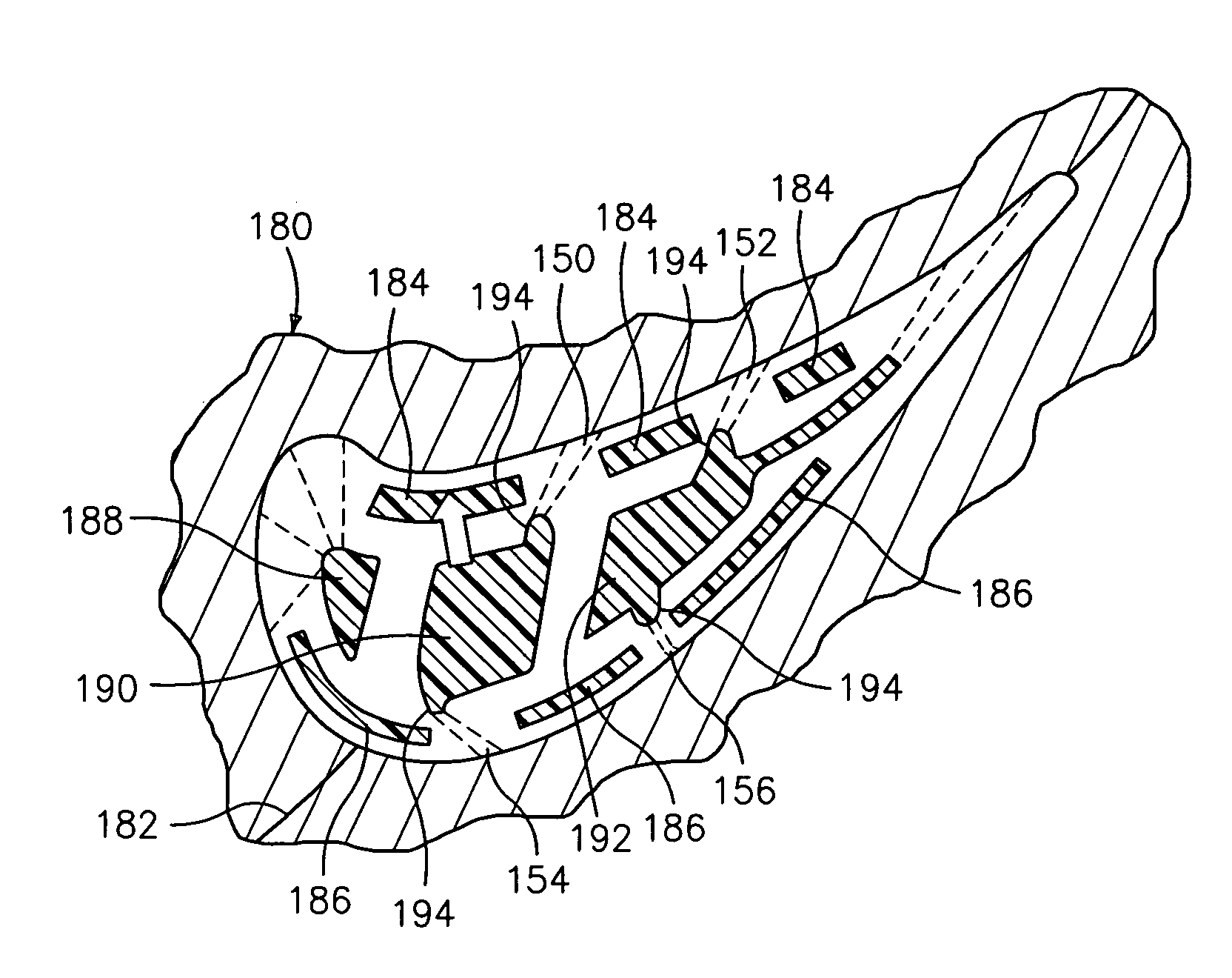
[0012]In accordance with the present invention, there is provided a turbine engine component having modifications which minimize thermal gradients, allows for film cooling, and avoid back flow margin problems as the film holes are fed with flow from the main supply cavities.

Problems solved by technology

In that case, the blade material will certainly melt and burn away.
As a result, this design leads to significant cooling flow reduction.
However, a low back flow will likely develop when cooling is extracted out of the peripheral circuit.

Method used


Image

  • High aspect ratio blade main core modifications for peripheral serpentine microcircuits
  • High aspect ratio blade main core modifications for peripheral serpentine microcircuits
  • High aspect ratio blade main core modifications for peripheral serpentine microcircuits

Examples


Embodiment Construction

)

[0023]Referring now to FIG. 5 of the drawings, there is shown an airfoil portion 100 of a turbine engine component such as a turbine blade. The turbine engine component may have other integrally formed elements such as a platform and a root portion, but for the sake of convenience these well known elements have not been illustrated in the drawings.

[0024]The airfoil portion 100 has a leading edge 102, a trailing edge 104, a pressure side wall 106 extending between the leading edge 102 and the trailing edge 104, and a suction side wall 108 also extending between the leading edge 102 and the trailing edge 104. Embedded within the pressure side wall 106 is a first cooling circuit 110. The cooling circuit 110 may have any desired configuration such as a serpentine configuration with three interconnected legs 112, 114, and 116 through which a cooling fluid flows. The serpentine configuration of the pressure side cooling circuit 110 may be that shown in FIG. 2b. Embedded within the suctio...


PUM


Abstract

A turbine engine component, such as a turbine blade, has an airfoil portion having a pressure side wall and a suction side wall, a first cooling circuit embedded within the pressure side wall, which first cooling circuit has at least two passageways embedded within the pressure side wall, a second cooling circuit embedded within the suction side wall, which second cooling circuit has at least two passageways embedded within the suction side wall, at least one cooling fluid supply cavity located between the pressure and suction side walls, each cooling fluid supply cavity having at least one projecting portion extending between adjacent ones of the embedded passageways in the first cooling circuit or adjacent ones of the embedded passageways in the second cooling circuit, and each projecting portion communicating with at least one film cooling hole. A method for forming the turbine blade component is also described.

Description

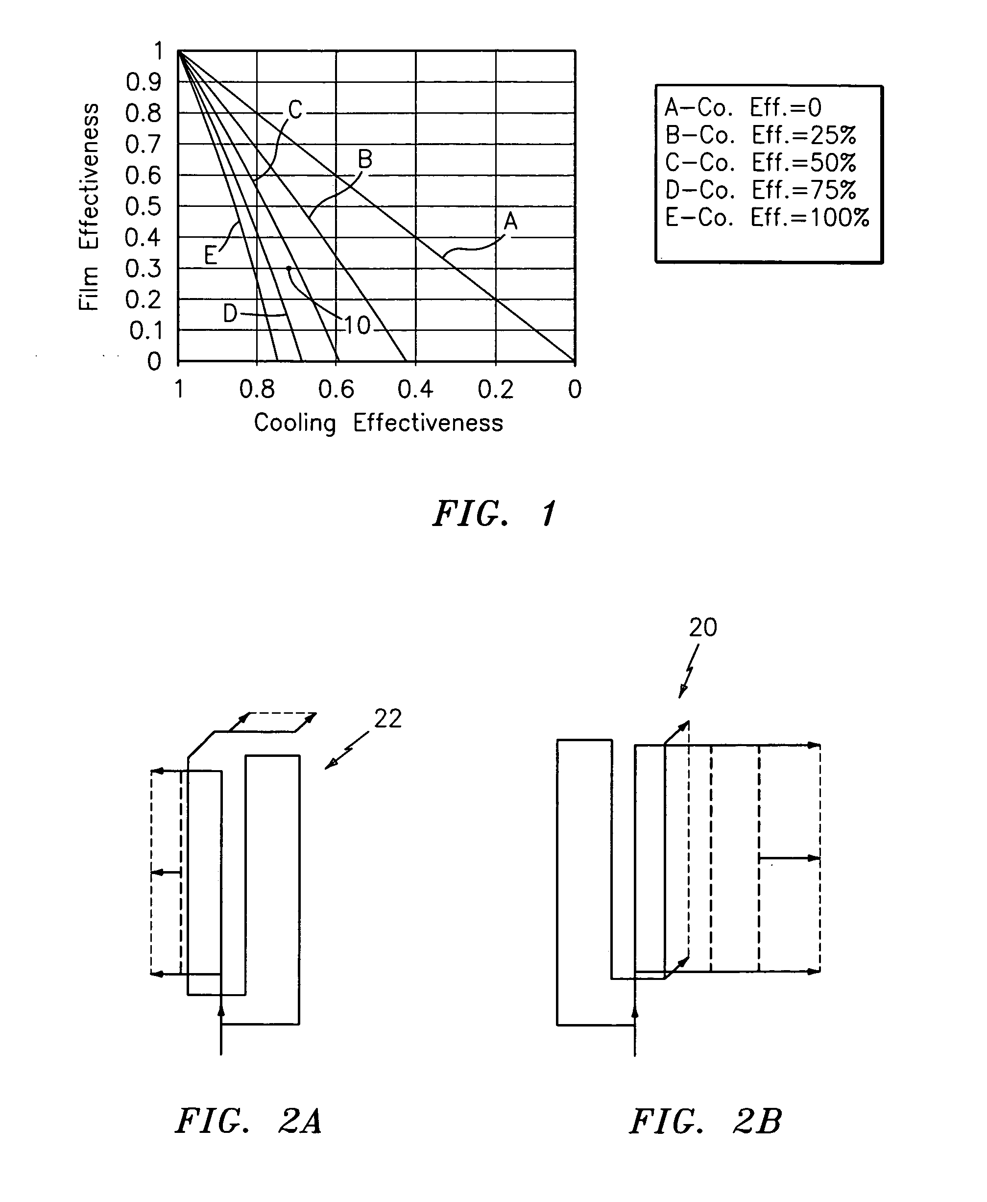
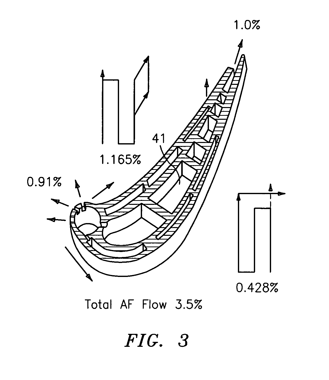
BACKGROUND[0001](1) Field of the Invention[0002]The present invention relates to a turbine engine component, such as a turbine blade, having modifications which minimize thermal gradients, allows for film cooling, and avoid back flow margin problems as the film holes are fed with a flow of cooling fluid from the main supply cavities.[0003](2) Prior Art[0004]The overall cooling effectiveness is a measure used to determine the cooling characteristics of a particular design. The non-achievable ideal goal is unity. This implies that the metal temperature is the same as the coolant temperature inside an airfoil. The opposite can also occur where the cooling effectiveness is zero implying that the metal temperature is the same as the gas temperature. In that case, the blade material will certainly melt and burn away. In general, existing cooling technology allows the cooling effectiveness to be between 0.5 and 0.6.[0005]More advanced technology, such as supercooling, should be between 0.6...

Claims


Application Information

Patent Timeline
IPC IPC(8): F01D5/18
CPCB22C9/04B22C9/103F01D5/186F05D2260/202F05D2250/185Y02T50/676F01D5/187Y02T50/60
Inventor CUNHA, FRANCISCO J.GAYMAN, SCOTT W.
Owner RAYTHEON TECH CORP
Learn More