Flexible joint with bellows

a flexible joint technology, applied in the direction of couplings, mechanical devices, drilling pipes, etc., can solve the problem of the height of the casing body

Active Publication Date: 2008-06-12
HUTCHINSON SA
View PDF10 Cites 8 Cited by
  • Summary
  • Abstract
  • Description
  • Claims
  • Application Information

AI Technical Summary

Benefits of technology

[0012]For a given diameter, the flexible joint as defined above makes it possible to save a considerable amount of height, e.g. 30%. This makes it possible in particular to reduce the height of the casing body, which is difficult to make because of the pressure it needs to accommodate.
[0013]The flexible pressure-compensation element may be made in the form of an annular diaphragm or else by one or more corrugated bellows or in the form of a diaphragm presenting a closure at one end. The or each compensation bellows is / are advantageously housed in an annular region about an axis constituted by said main axis. The variant with a diaphragm bellows makes it possible to compensate pressure variations more precisely and more quickly because of lower stiffness, and also to compensate a larger volume of fluid.
[0016]In order to avoid the bottom tube rising and thereby damaging the laminated ball joint, the casing cover is advantageously coupled to a cylindrical extension disposed in the flow space and housing the coupling bellows, at least in part. This cylindrical extension also makes it possible to avoid problems of turbulence due to the stream of liquid passing close to the undulations of the bellows (vibrations of the bellows).

Problems solved by technology

This makes it possible in particular to reduce the height of the casing body, which is difficult to make because of the pressure it needs to accommodate.

Method used


Image

  • Flexible joint with bellows
  • Flexible joint with bellows
  • Flexible joint with bellows

Examples


Embodiment Construction

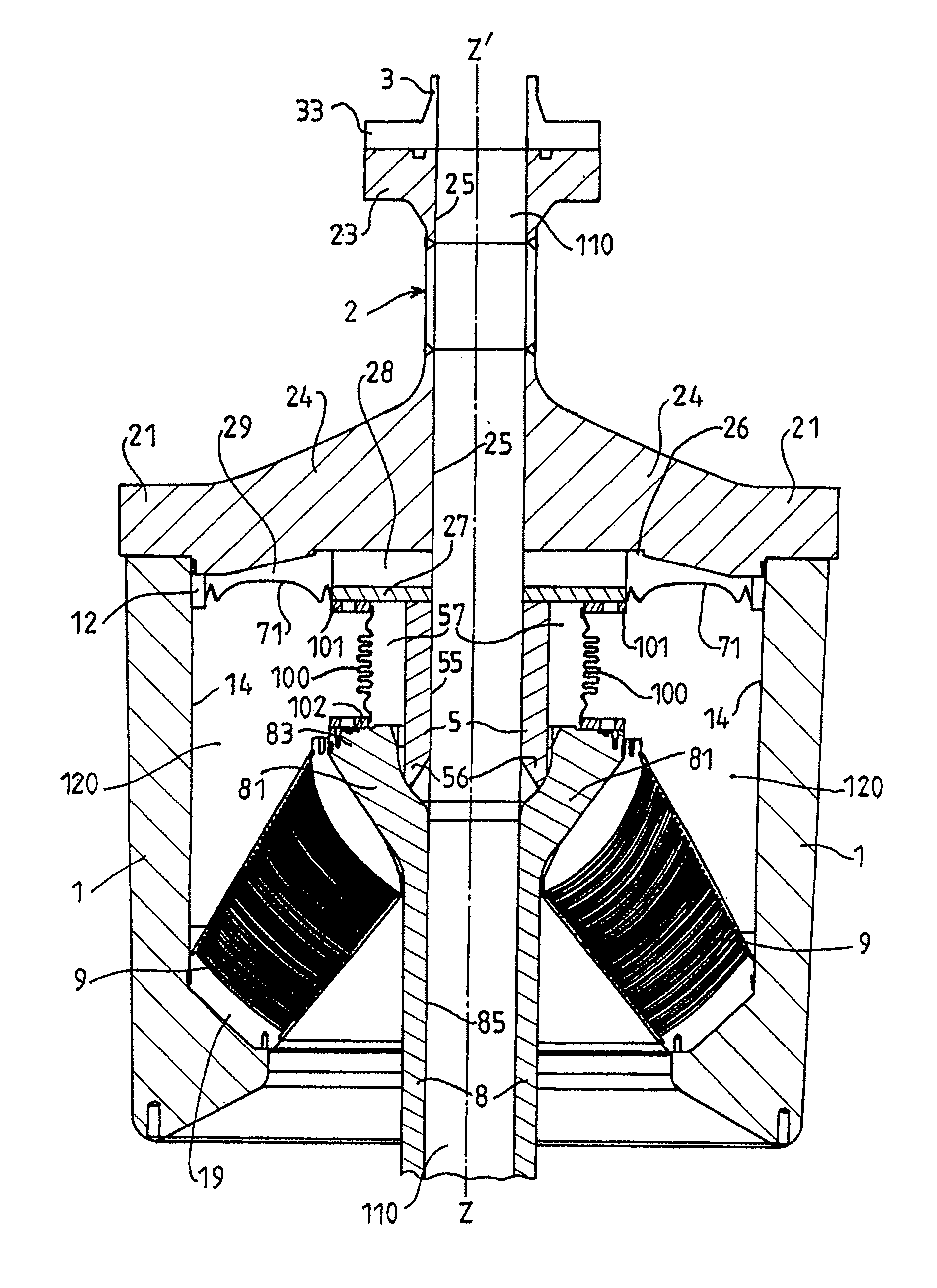
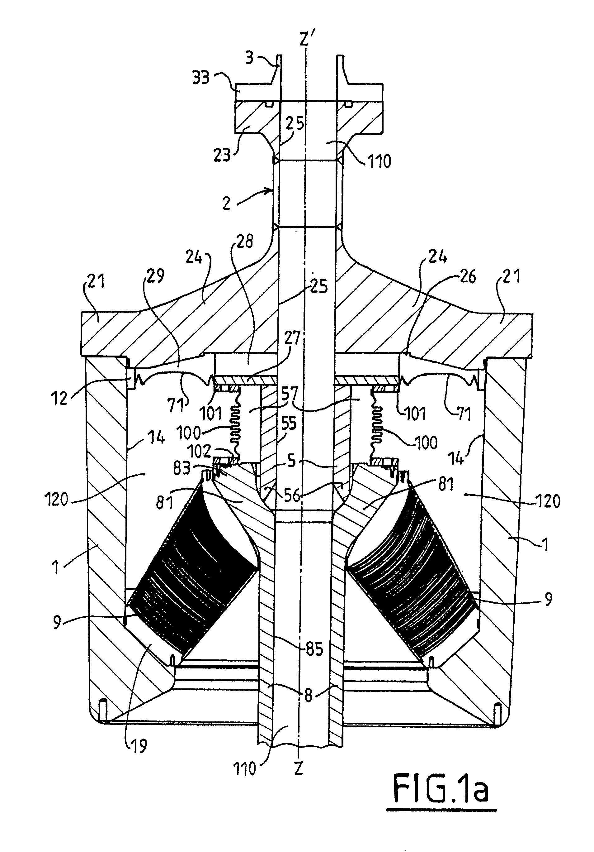
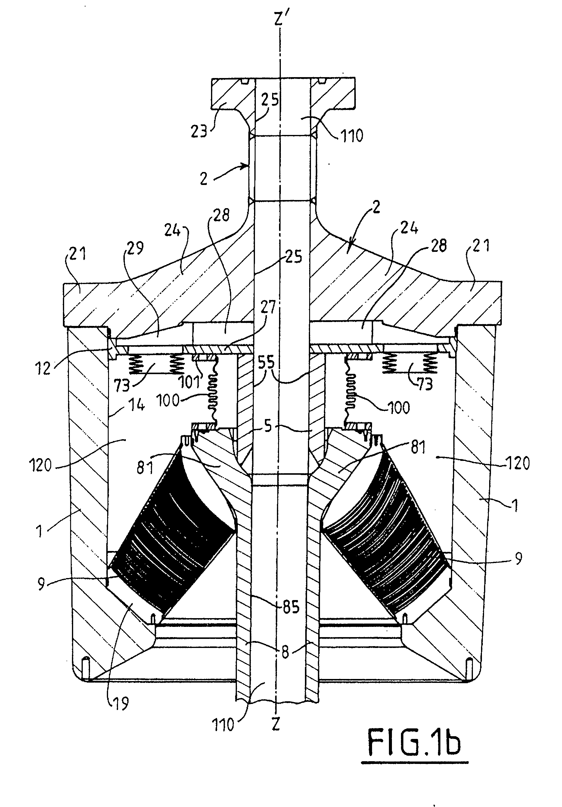
[0018]The flexible joint shown seeks to provide a connection between two tubes 3 and 8 for transferring fluid under high pressure in an undersea oil installation.

[0019]One of the tubes, referenced 3, presents a flange 33 mounted on a flange 23 of a cover 2 of a casing that presents a casing body 1. The cover 2 presents an enlarged base 24 enabling it to be mounted by tie bars on the body 1 of the casing, while defining in particular a main chamber 120 filled with an incompressible fluid.

[0020]At its bottom end, the body 1 receives on its circular concave periphery 19 a laminated ball joint 9 constituted in known manner by alternating layers of metal and layers of elastomer that are bonded together. The laminated ball joint 9 is secured to the periphery 19, and at its other end that is in the form of a circular arc in section, it is secured to a flared extension 81 of the tube 8.

[0021]The end 83 of the extension 81 receives a seal-maintaining element 102 at the end of a corrugated me...


PUM


Abstract

The invention relates to a flexible joint with bellows for coupling two tubular elements together for passing fluid in a flow space and presenting a main axis that is constituted by the axis common to the tubular elements when they are in their aligned position, and including at least one flexible joint element functionally connected to a first tubular element and to a casing, together with a coupling bellows coupling together the two tubular elements, the coupling bellows, the flexible joint element, and the casing defining walls of a fluid-filled cavity. The joint including a flexible pressure-compensation device spaced apart from the bellows and having a first face forming at least part of a wall of said cavity and a second face that is in communication with the flow space.

Description

CROSS REFERENCE TO RELATED APPLICATIONS[0001]This application claims priority from French patent application 06 / 10668 filed Dec. 7, 2006.[0002]The present invention relates to a flexible joint with bellows suitable for constituting a flexible hinge between two tubular elements, in particular in undersea oil installations, and more particularly in installations subjected to high pressures and / or to large variations in internal pressure.BACKGROUND OF THE INVENTION[0003]Flexible joints make use of at least one flexible joint element, in particular a laminated joint, e.g. a ball joint made up of alternating layers of metal and of rubber.[0004]The combination of large variations in pressure together with the action of gas dissolved in the fluid being conveyed leads to problems of bubbles of gas absorbed within the rubber decompressing rapidly.[0005]U.S. Pat. No. 5,133,578 relates to a ball joint between two moving tubes (a so-called “floating” connection) using two symmetrical laminated ...

Claims


Application Information

Patent Timeline
Patent Type & Authority Applications(United States)
IPC IPC(8): F16D3/00
CPCE21B17/085F16L27/11F16L27/103
Inventor FORGES, HERVE RICHER DECIOLCZYK, JEAN-PIERRE
Owner HUTCHINSON SA
Why Eureka
Try Eureka