Method and apparatus for analyzing the variable operating rate of a manufacturing process

a manufacturing process and variable operating rate technology, applied in the field of methods and apparatus for analyzing the variable operating rate of a manufacturing process, can solve the problems of no automated control system that currently controls the operating speed, the selected speed may be considerably far from the optimal operating speed, and the speed might be less desirable. to achieve the effect of maximizing profitability

Inactive Publication Date: 2008-06-12
HOFFMAN ROGER P
View PDF4 Cites 12 Cited by
  • Summary
  • Abstract
  • Description
  • Claims
  • Application Information

AI Technical Summary

Benefits of technology

[0045]Production planning plays the same role as it would typically play in any production facility except for the fact that the size of the facility changes with each planning cycle so as to maximize profitability. It is an object of the present invention for the planner to bring order from chaos for example, making certain that the customer gets full truck loads of several products, and that it does not require holding excess inventory to accomplish this. It is an object of the present invention for the planner to have rules that are necessary to keep things coordinated.

Problems solved by technology

This is a faulty assumption: faster might actually be less desirable.
There are, in other words, no automated control systems that currently control the operating speed in response to productive efficiency of a manufacturing machine.
This selected speed may be, however, considerably far from the optimal operating speed.
Further, changes to the operations that effect efficiency can occur rapidly, while manual reactions based on operator observations typically lag considerably behind.
This lack of complete information and timely reaction greatly reduces the efficiency of the equipment operation.
For example, when production is to be decreased, either manual input or machine controls first decrease the steam pressure in the dryer cans, which in turn increase the moisture content of the paper.
This is typical of many automatic adjustments to operating speed, which are affected by a forced change in quality, such as increased moisture content.
While unacceptable quality and breaks occur at all acceptable machine operating speeds, increased frequency of breaks and diminishment of quality occurs as the operating speed increases.
Current automated machine controls do not maximize efficiency by taking into account the loss of unacceptable quality and breaks for determining the appropriate operating speed of a machine.
Aside from providing information on quality and breaks, current machine and information system controls do not aid in the adjustment of the machine production to achieve the most efficient or optimal operating speed.
While the higher limit may be established on a criteria that factors in an estimate of bleaching costs, the pulp mill control system does not actually calculate the cost of additional bleaching.
There are no control features presently available that limit the digester operation speed based on the actual current marginal cost of the additional bleaching.
When all variables are considered, however, it may be discovered that the additional bleaching action required on a certain level of marginal operating speed may be measured to actually reach $100 per ton due to the non-proportional demands for bleaching chemicals, energy, and effluent treatment.
Current controls do not calculate from the necessary variables the total additional bleaching cost on the marginal operating speed, and subsequently limit digester operations to not incur the additional inefficient bleaching.
When the machine controls recognizes an inventory depletion of pulp from high density storage, machine speed or steam pressure to the dryers may be limited to decrease machine operating speed to allow pulp storage to replenish or “catch-up” to desired levels of operation.
One problem with current control systems is that they are strictly focused on either one particular piece of equipment's operating characteristics, or at best, focus on monitoring the availability of inflow materials for the piece of equipment.
Current controls do not, however, monitor many, or even most, manufacturing inflows from the time of introduction into the process.
An additional problem with current control systems is that any measured efficiency on marginal operating speed is based solely on quantitative and qualitative measurements, rather than total economic efficiency.
In making equipment operating speed decisions, the current control systems fails to account for the price component of the economic efficiency of a particular activity.
These industries are suffering from inefficiencies due to inadequate integrated control systems that factor in marginal operating speeds.

Method used


Image

  • Method and apparatus for analyzing the variable operating rate of a manufacturing process
  • Method and apparatus for analyzing the variable operating rate of a manufacturing process
  • Method and apparatus for analyzing the variable operating rate of a manufacturing process

Examples


Embodiment Construction

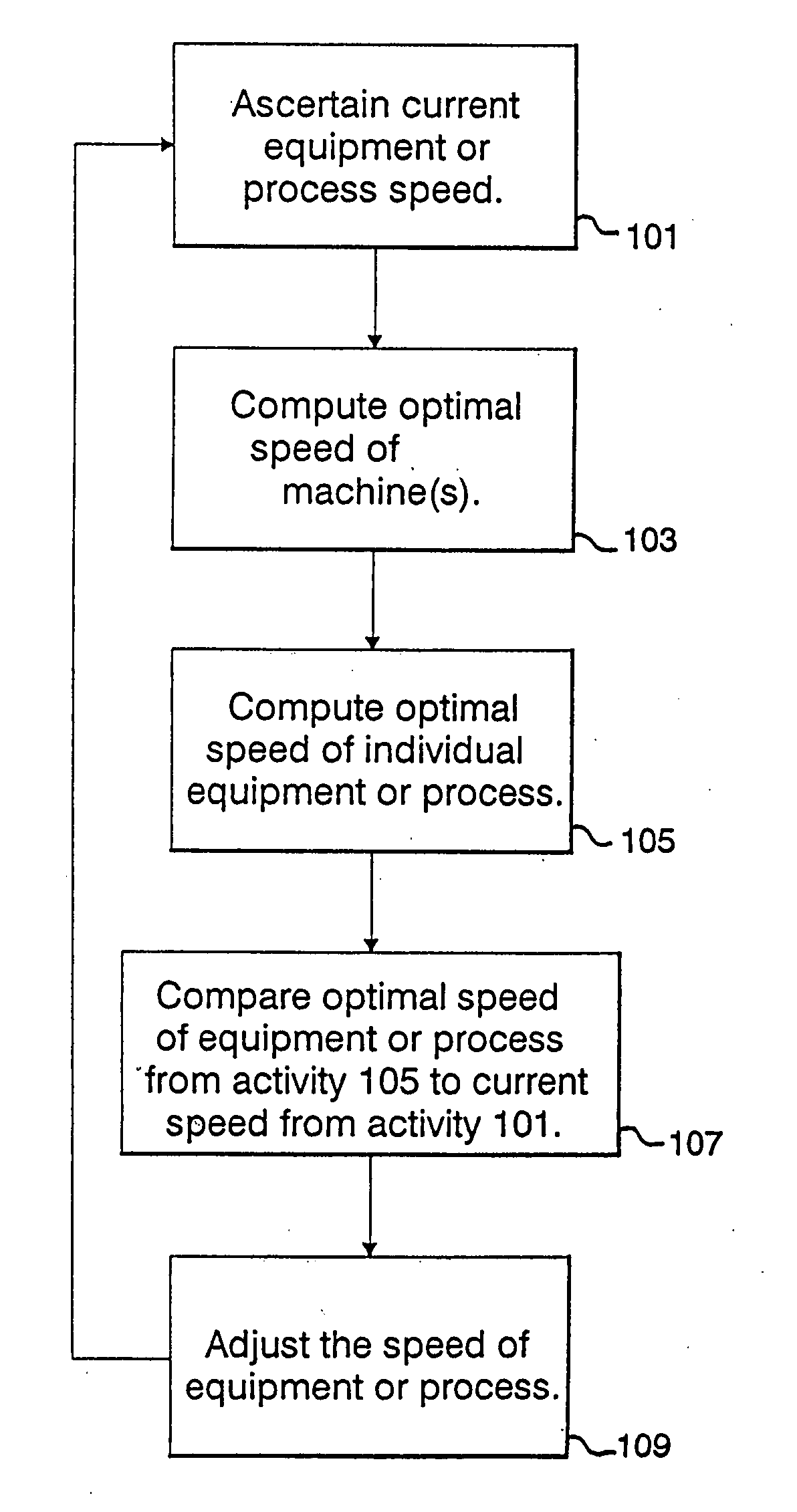
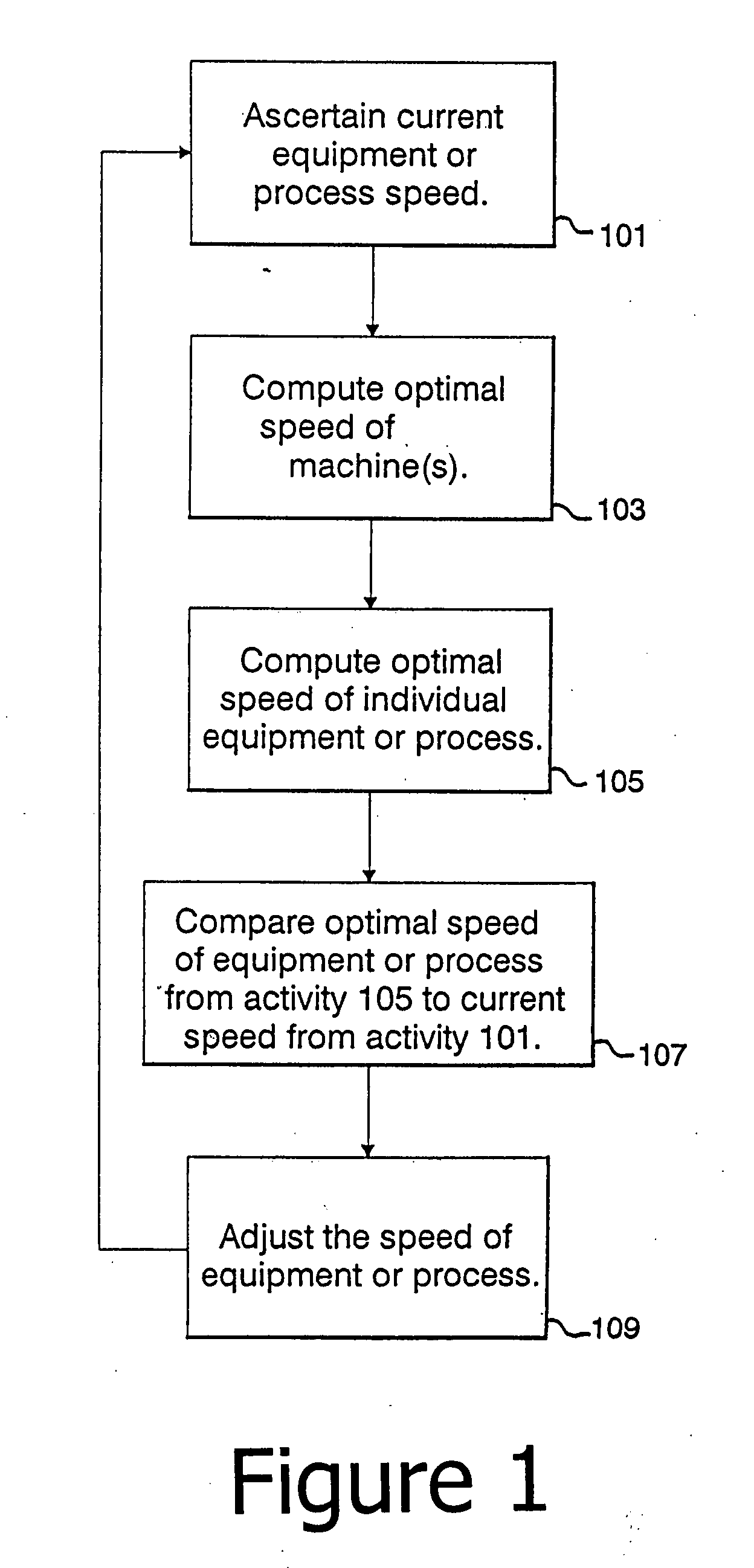
[0053]The present invention is, in one embodiment, a method and apparatus for an integrated control system in a manufacturing facility, or computer program implementing the system, that establishes and implements an optimal operating speed for equipment or processes that enhances the efficiency of the entire activity involved in a manufacturing facility. The present invention can be utilized in a number of manufacturing businesses, particularly process manufacturing, such as steel (and the production of other metals), petroleum and energy. The use of a papermaking facility example in the description is not meant to limit the scope of the invention to the paper industry.

[0054]The use of the term manufacturing facility in this application shall include any manufacturing plant, any single piece of equipment or process, or groups of equipment or processes that includes a manufacturing activity for the manufacture of a product. The use of the term also could include groups of facilities,...


PUM


Abstract

The present invention relates generally to a method and apparatus for analyzing the variable operating rate of a manufacturing process. The system contains information relating to procurement activity, manufacturing activity and sales and marketing activity.

Description

RELATED APPLICATIONS[0001]This is a Continuation-In-Part of U.S. application Ser. No. 09 / 679,119 filed Oct. 4, 2000, now pending which is a continuation-in-part of U.S. Pat. No. 6,157,916 issued Dec. 5, 2000.FIELD OF THF INVENTION[0002]The present invention relates generally to a method and apparatus for analyzing the variable operating rate of a manufacturing process.BACKGROUND OF THE INVENTION[0003]Current control systems of the machinery and processes of a facility in the manufacturing industry generally run equipment and processes as fast as possible, while maintaining a set level of quality. The focus of control is on the current and historical operating characteristics of the particular piece of equipment, with a particular emphasis on output quality. The controls are sometimes designed to maintain maximum operating speed and the operator manually assesses and controls operations to maintain a targeted acceptable quality. Conversely, the controls may be designed to assess the ...

Claims


Application Information

Patent Timeline
Patent Type & Authority Applications(United States)
IPC IPC(8): G06Q10/00G07G1/00G06F17/30G06Q30/00G05B19/418G06Q30/02
CPCG05B19/41865G05B2219/32252G05B2219/32253G06Q30/0206G05B2219/34418G06Q30/018G05B2219/32265Y02P90/02
Inventor HOFFMAN, ROGER P.
Owner HOFFMAN ROGER P
Why Eureka
Try Eureka