

Monitor Control of Devices Connected to Network
- Summary
- Abstract
- Description
- Claims
- Application Information
AI Technical Summary
Benefits of technology
Problems solved by technology
Method used
Image

Examples
first embodiment
A. First Embodiment
[0100]A1. Configuration of Device Management System
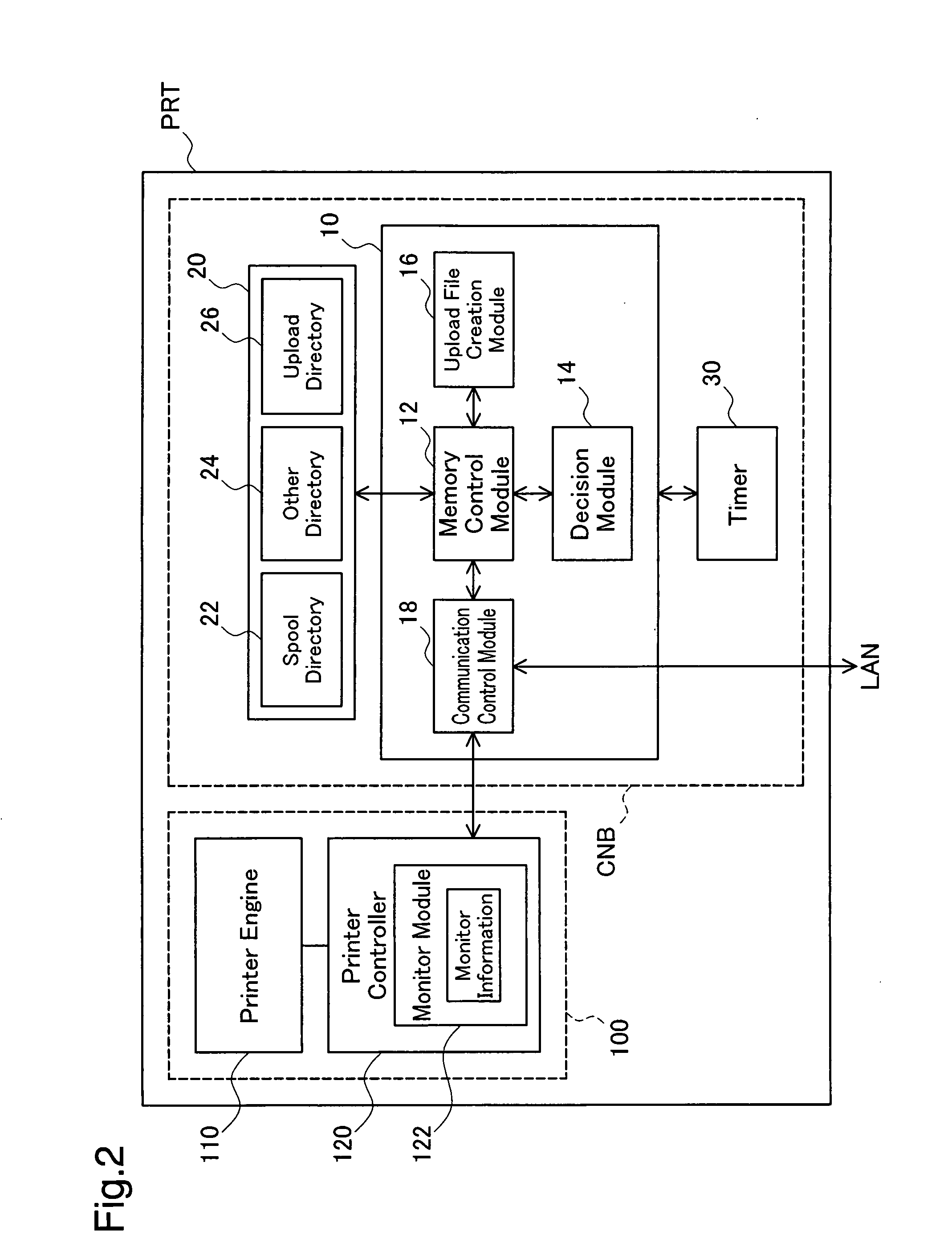
[0101]A2. Structure of Printer
[0102]A3. Printer General Operation Flow
[0103]A4. FTP Command Process
[0104]A5. Upload Process
B. Second Embodiment
C. Third Embodiment
D. Fourth Embodiment
E. Fifth Embodiment
[0105]E1. Structure of Printer
[0106]E2. Printer General Operation Flow
[0107]E3. File Collection Process
[0108]E4. Upload Process
F. Second Embodiment
G. Third Embodiment
H. Fourth Embodiment
I. Modifications
A. First Embodiment
A1. Configuration of Device Management System
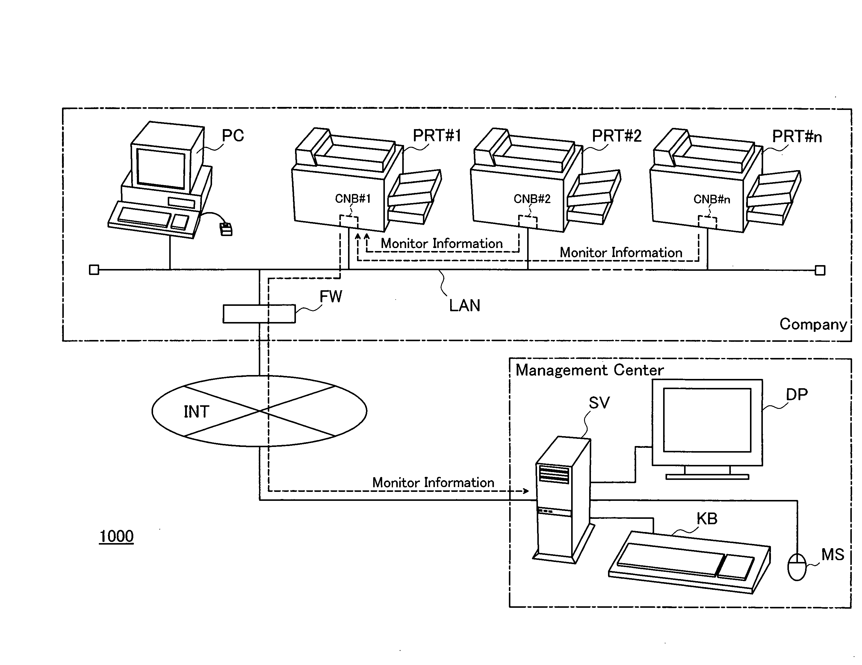
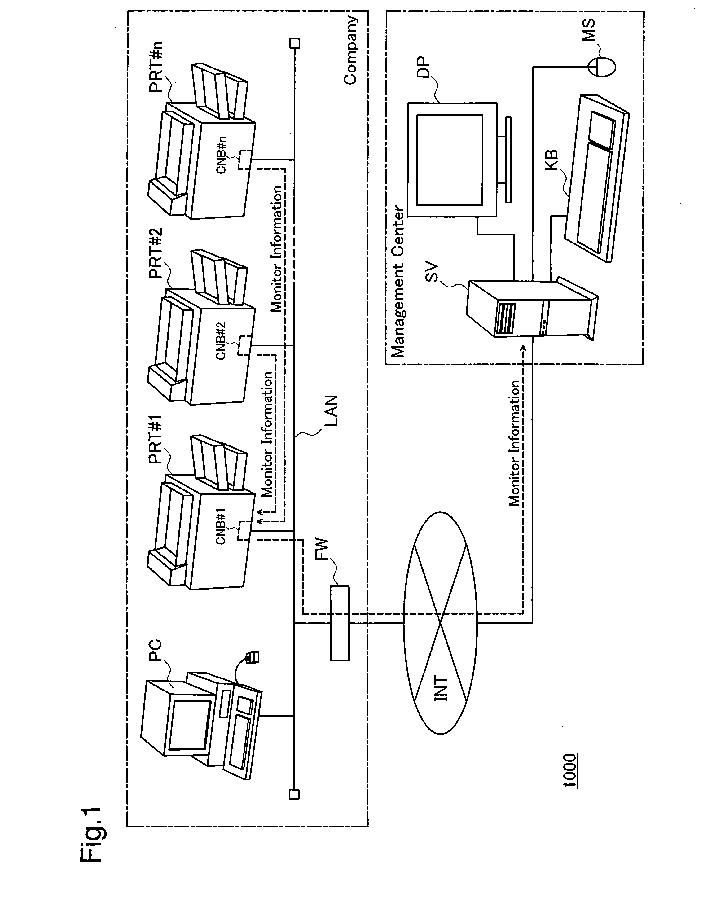
[0109]FIG. 1 schematically illustrates the configuration of a device management system 1000 in a first embodiment of the invention. The device management system 1000 includes a management server SV in a management center and an intra-company local area network LAN that is connected to the management server SV via the Internet INT. There is a firewall FW provided between the local area network LAN and the Internet INT to prohibit accesses from the Internet ...
second embodiment
B. Second Embodiment
[0147]A device management system 1000 of a second embodiment has the same configuration as that of the device management system 1000 of the first embodiment. Each printer PRT in the second embodiment has the same structure as that of the printer PRT in the first embodiment. The processing executed by the CPU 10 of the custom network board CNB attached to the printer PRT of the second embodiment is partially different from the processing executed by the printer PRT of the first embodiment. The following describes the difference from the first embodiment.
[0148]FIG. 8 is a flowchart showing a general operation flow of the printer PRT executed in the second embodiment. The processing flow of FIG. 8 is executed instead of the processing of step S310 in the general operation flow of the first embodiment (see FIG. 4). In the second embodiment, the representative printer sends a delayed upload request to the represented printers in the case of successful upload of the up...
third embodiment
C. Third Embodiment
[0159]A device management system 1000 of a third embodiment has the same configuration as that of the device management system 1000 of the first embodiment. Each printer PRT in the third embodiment has the same structure as that of the printer PRT in the first embodiment. The processing executed by the CPU 10 of the custom network board CNB attached to the printer PRT of the third embodiment is partially different from the processing executed by the printer PRT of the first embodiment. The following describes the difference from the first embodiment.
[0160]FIG. 10 is a flowchart showing a general operation flow of the printer PRT executed in the third embodiment. The processing flow of FIG. 10 is executed instead of the processing of step S310 in the general operation flow of the first embodiment (see FIG. 4). In the third embodiment, each represented printer stores a deletion time Td into the memory 20 when the monitor information file is deleted in response to th...
PUM
 Abstract
Description
Claims
Application Information