
Crossbow

a crossbow and bow technology, applied in bows/crossbows, white arms/cold weapons, weapons, etc., to achieve the effect of simple operation

Inactive Publication Date: 2008-06-19
OGAWA TSUYOSHI
View PDF7 Cites 19 Cited by
  • Summary
  • Abstract
  • Description
  • Claims
  • Application Information

AI Technical Summary

Benefits of technology

[0007]The invention aims at providing a crossbow that enables arrows to be continuously shot with simple operation in view of such as problem.
[0011]Accordingly, a plurality of arrows are set in the cylinder, the string is pulled, and is hooked, and cocked to the wire catch, and the cylinder is rotated, so that arrows can be shot one after another. In this way, arrows can be continuously shot with simple operation.

Problems solved by technology

However, in a conventionally well-known crossbow, once an arrow was shot, it took time to shoot the next arrow.

Method used


Image

  • Crossbow
  • Crossbow
  • Crossbow

Examples


second embodiment

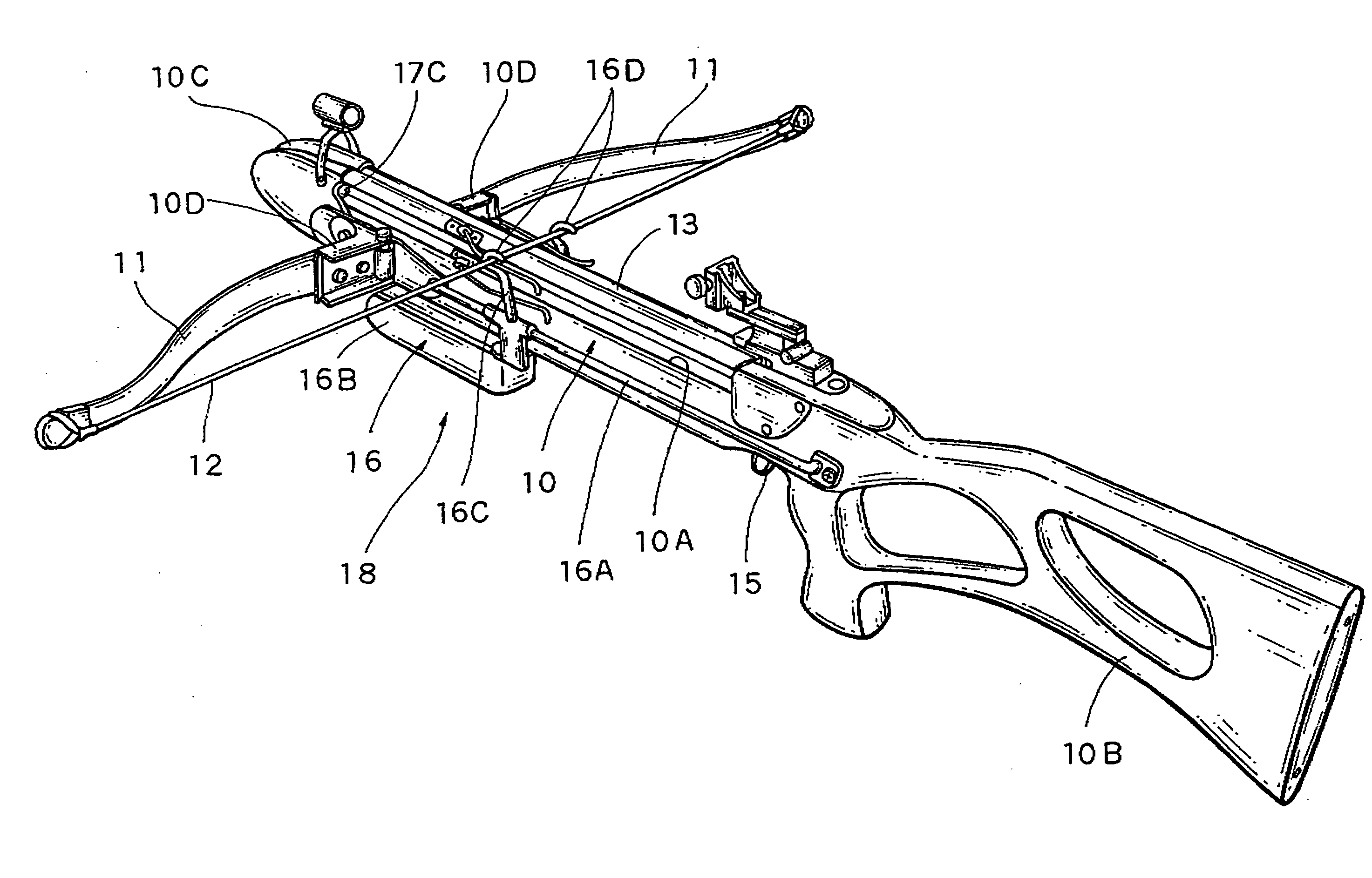
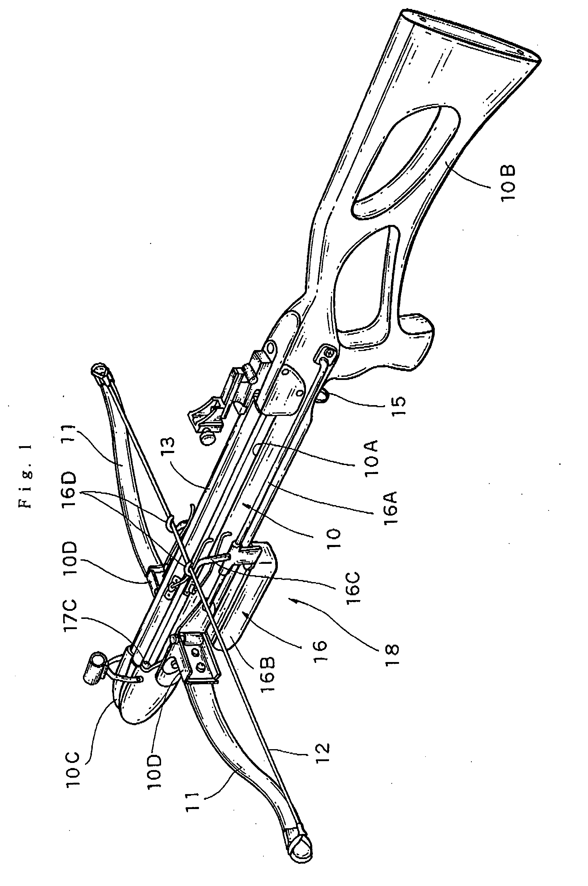
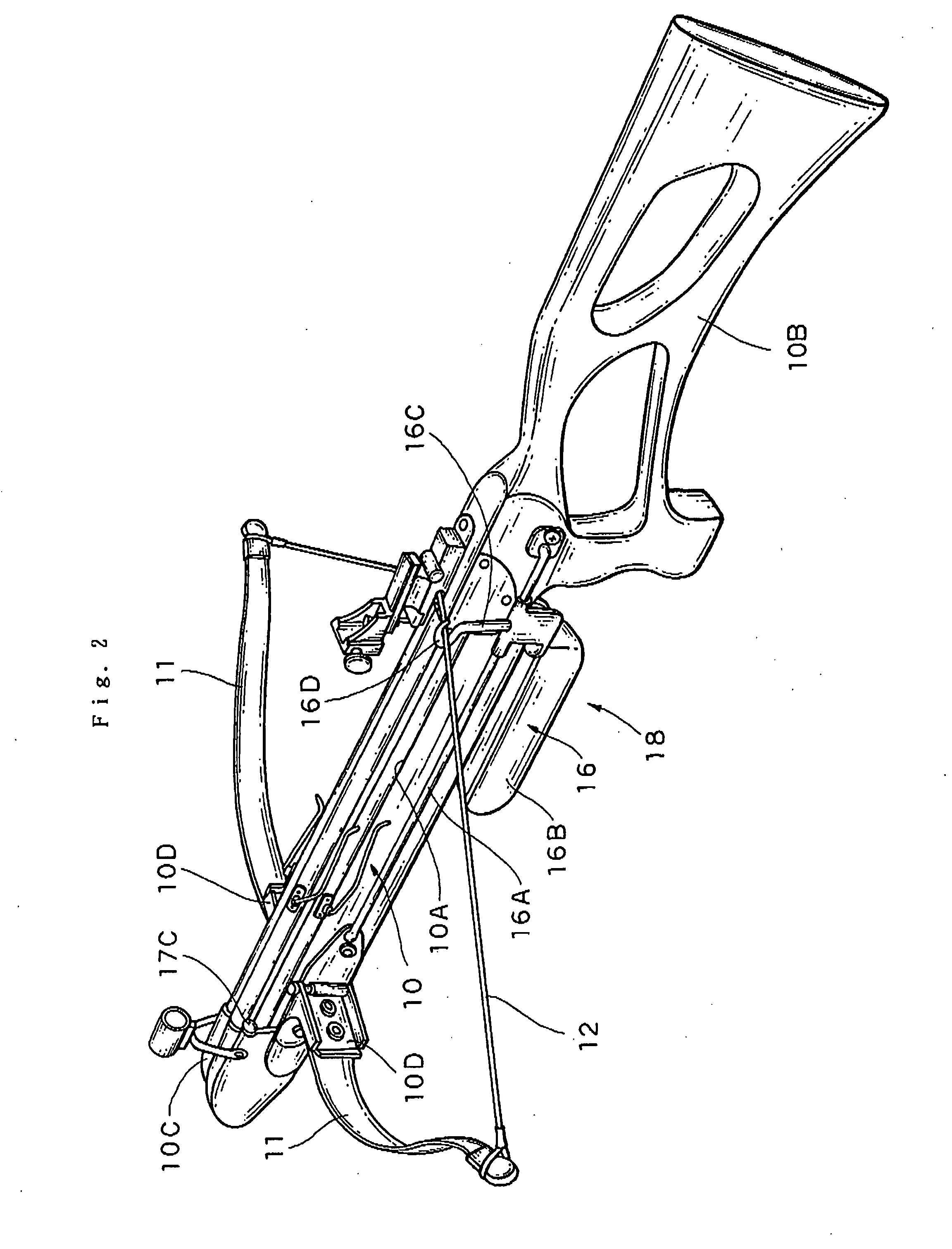
[0051]FIGS. 7 to 9 show a In these figures, the same reference numerals as those of FIGS. 1 to 6 represent the same or equivalents parts. In this embodiment, a cocking lever 16B′ is used for an operating mechanism 16′ of a cocking device 18′. Specifically, both lateral guide bars 16A of the bow stock 10 are provided, and a tubular base of the cocking lever 16B′ is slidably fitted on both the guide bars 16A, and the cocking lever 16B′ is foldably configured. Moreover, arms 16C′ are formed integrally with the tubular base. The arms 16C′ extend upward, and tips of the arms are formed with pallets 16D′ to which the string 12 of the bow 11 is hooked.

[0052]In this embodiment, the folded cocking lever 16B′ is made to slide to the forefront, and the string 12 of the bow 11 is hooked on the pallets 16D′. Next, when the cocking lever 16B′ is unfolded, a front grip of the cocking lever 16B is gripped and pulled rearward, the pallets 16D′ are pulled rearward while the string 12 bends the bow 1...

first embodiment

[0053]Since the other operation is the same as that of the first embodiment, detailed description thereof is omitted herein.

third embodiment

[0054]FIGS. 10 and 11 show a In these figures, the same reference numerals as those of FIGS. 1 to 6 represent the same or equivalents parts. In this embodiment, a shaped part 10B similar to a grip and a butt of a rifle is used for an operating mechanism 16″ of a cocking device 18″.

[0055]Specifically, a lower front end of the shaped part 10B similar to a grip and a butt of a rifle is provided so as to be rotatable with respect to the bow stock 10 by a shaft 10B-1. A tubular part of a slide plate 16E″ is slidably fitted on both lateral guide bars 16A″ of the bow stock 10. A front end of a link 16F″ is fixed to the tubular part of the slide plate 16E″, and a rear end of the link 16F″ is connected with an upper front end of the shaped part 10B similar to a grip and a butt of a rifle.

[0056]Further, arms 16C″ are formed integrally with the slide plate 16E″. The arms 16C″ extends upward, and tips of the arms are formed with pallets”16D to which the string 12 of the bow 11 is hooked.

[0057]...


PUM


Abstract

A crossbow that enables arrows to be shot with simple operation is provided. The crossbow includes a bow stock that has a fitting recess for a cylinder formed between a front end and a rear end thereof, a bow that is attached to the front end of the bow stock thereacross, and has a string tensioned between both ends thereof, a wire catch that is rockably provided at the rear end of the bow stock to hook the tensioned string, a trigger that is provided at the rear end of the bow stock to cock the wire catch that has hooked the string and to release the cocking of the wire catch by triggering, thereby shooting an arrow, a cylinder that is rotatably fitted in the fitting recess of the bow stock, and has a plurality of arrow grooves formed at predetermined angular intervals in an outer peripheral surface thereof so as to extend in a longitudinal direction, and has arrows slidably inserted in the plurality of arrow grooves, respectively, and a rotation operating mechanism that rotates the cylinder at every predetermined angle, and locates one arrow groove in front of the wire catch.

Description

BACKGROUND OF THE INVENTION[0001]1. Field of the Invention[0002]The present invention relates to a crossbow, and specifically, to a crossbow that enables arrows to be continuously shot with simple operation.[0003]2. Discussion of the Related Art[0004]It is considered that a crossbow originates in the Eastern crossbow that appeared around the fifth century B.C., and has become almost the current shape in Europe around the twelfth century.[0005]In this crossbow, a method of attaching a bow to a tip of a bow stock (pedestal) across it, pulling the string of a bow to hook it on a wire catch, locking an arrow that is thicker and shorter than a normal one called a bolt or quarrel to the string, and pulling a trigger to release the string from the wire catch, thereby shooting the arrow is basically adopted (Japanese Utility Model Application Publication Nos. 61-79793 and 58-52498).SUMMARY OF THE INVENTION[0006]However, in a conventionally well-known crossbow, once an arrow was shot, it too...

Claims


Application Information

Patent Timeline
IPC IPC(8): F41B5/14
CPCF41B5/12F41B5/1469F41B5/14F41B5/126
Inventor OGAWA, TSUYOSHI
Owner OGAWA TSUYOSHI
Learn More