Vibration isolator, and method of mounting the same

a technology of vibration isolator and isolator, which is applied in the direction of shock absorbers, manufacturing tools, machine supports, etc., can solve the problems of difficult connection of dynamic dampers to inner tubes, difficult to reduce total manufacturing costs, etc., and achieves the effect of reducing vibration, eliminating work, and reliably transmitting vibration caused

Active Publication Date: 2008-06-19
PROSPIRA CORP +1
View PDF7 Cites 13 Cited by
  • Summary
  • Abstract
  • Description
  • Claims
  • Application Information

AI Technical Summary

Benefits of technology

[0013]According to the vibration isolator of the first aspect of the invention, the vibration generating section is connected with the vibration receiving section through the elastic body, so that when vibration occurs in the vibration generating section, it is possible to reduce the vibration that would otherwise be transmitted to the vibration generating section to the vibration receiving section because the elastic body can damp and absorb the vibration through its elastic deformation.
[0014]Furthermore, according to the vibration isolator of the first aspect of the invention, one end of the connecting member is fitted into the inner peripheral side of the inner tube and the other end of the connecting member is fitted into the inner peripheral side of the supporting member, thereby connecting the supporting member to the inner tube via the connecting member. The mass and the elastic connector are hence connected to the inner tube via the connecting member and the supporting member. It is therefore possible to reliably transmit the vibration caused in the other one of the vibration generating section or the vibration receiving section to the elastic connector and the mass via the connecting member and the supporting member.
[0015]Since the mass and the elastic connector function as a dynamic damper, by suitably setting the weight of the mass and the rigidity of the elastic connector so as to correspond to the resonance frequency of the other one of the vibration generating section or the vibration receiving section at this time, resonance vibration is also generated in the mass when the other one of the vibration generating section or the vibration receiving section causes vibration of the resonance frequency. The vibration level of the resonance vibration caused in the other one of the vibration generating section or the vibration receiving section may hence be effectively reduced by inertia force of the mass.
[0016]As a result, according to the vibration isolator of the first aspect of the invention, it is possible to provide the dynamic damper containing the mass and the elastic connector as a part of the apparatus, by connecting the mass and the elastic connector to the inner tube, and thereby to eliminate work for assembling the dynamic damper separately from the vibration isolator. Therefore, it is possible to reduce the total manufacturing cost of the vibration isolator and the dynamic damper.

Problems solved by technology

However, it is difficult to connect the dynamic damper to the inner tube while avoiding interference with the outer tube, the body and fastening members such as a bolt in the vibration isolator as described in Patent Literature 1.
Therefore, works for assembling the vibration isolator and the dynamic damper respectively to the weight trucks and the like have been required, increasing a number of their assembling steps, and it has been difficult to reduce the total manufacturing cost.

Method used


Image

  • Vibration isolator, and method of mounting the same
  • Vibration isolator, and method of mounting the same
  • Vibration isolator, and method of mounting the same

Examples


embodiment

Structure of Embodiment

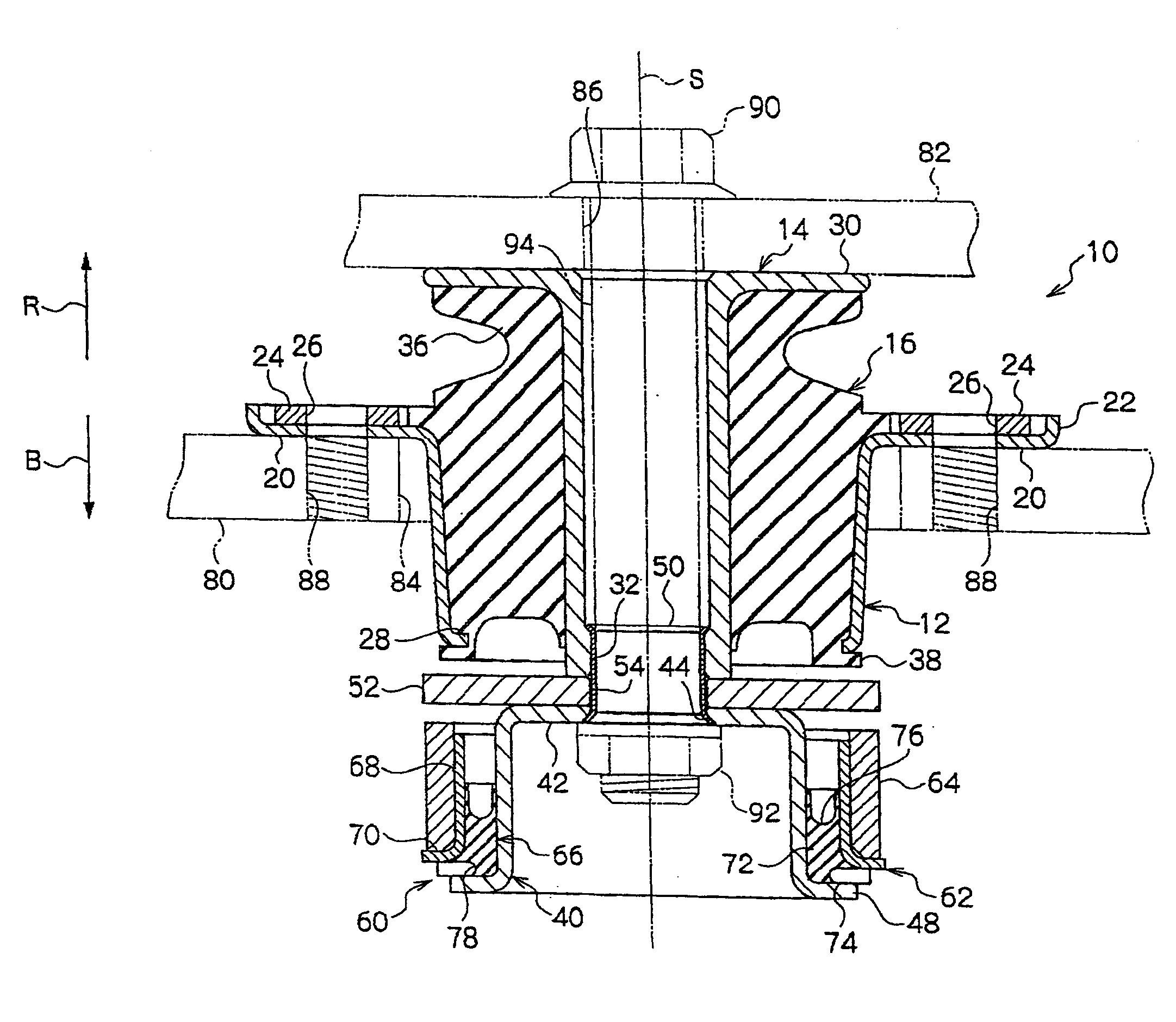
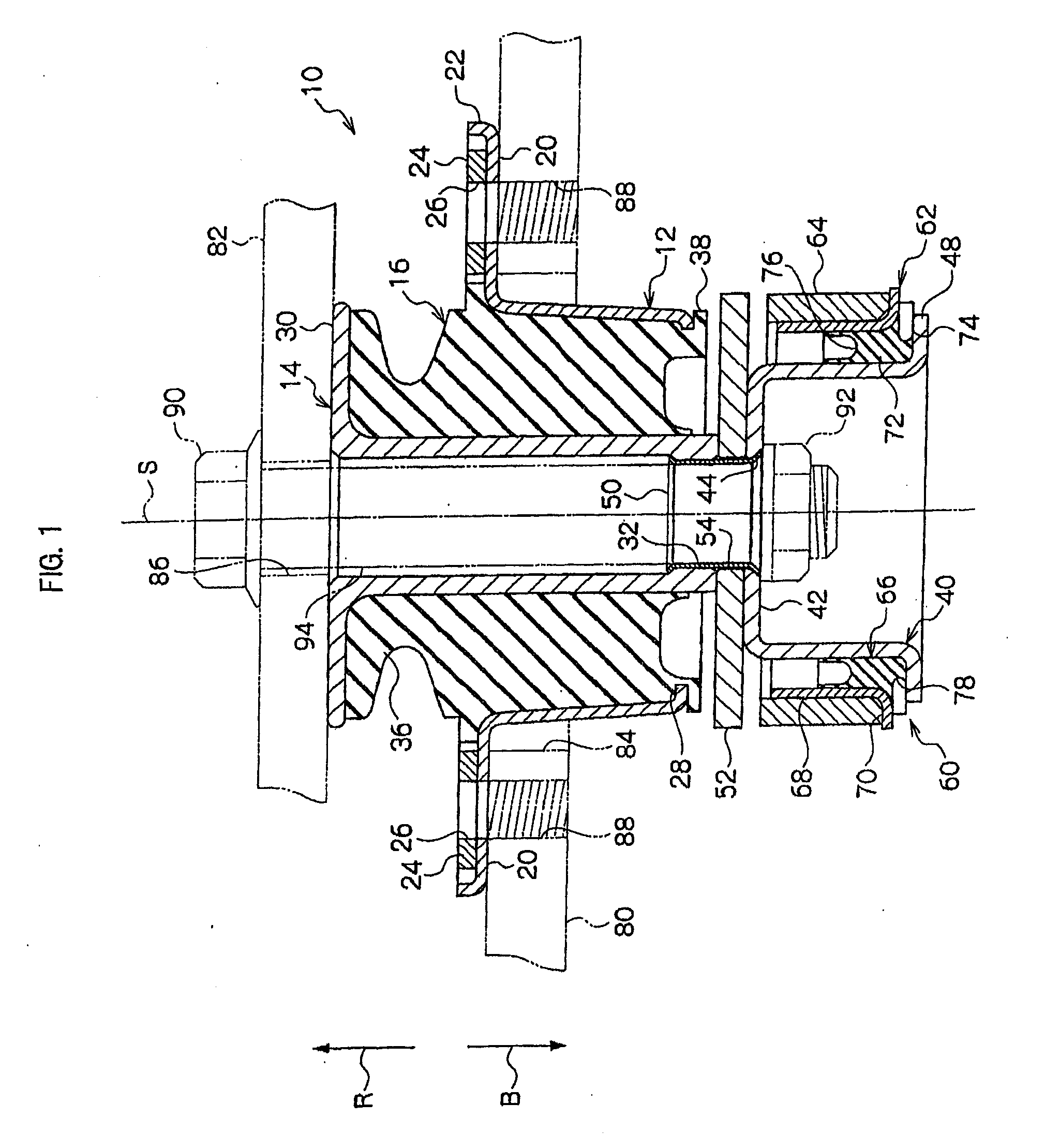
[0039]FIGS. 1 and 2 show a cab mount, i.e., the vibration isolator of the embodiment of the invention. The cab mount 10 is disposed between a car body 80, i.e., a lower traveling body of a truck and a part of passenger cars, and a cab 82, i.e., a drivers' cabin to mount the cab 82 on the car body 80 in a manner of vibration-free.

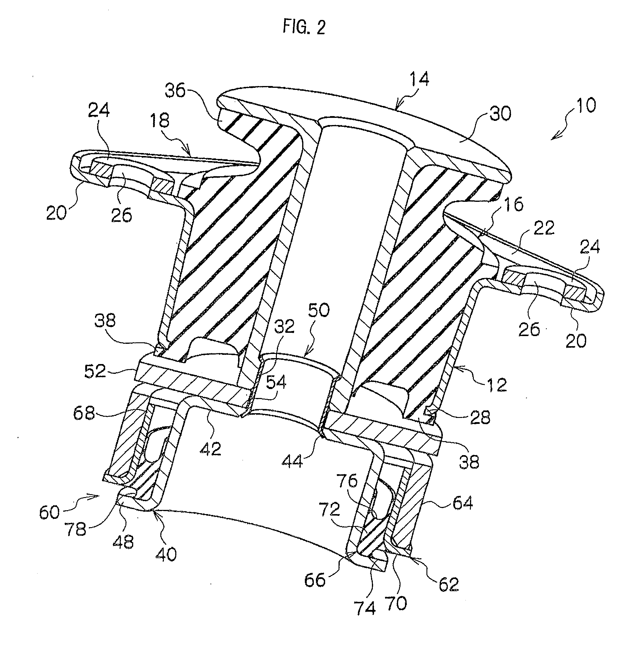
[0040]As shown in FIG. 2, the cab mount 10 is formed substantially into a columnar shape as a whole. The cab mount 10 is provided with an outer cylindrical fitting 12 formed substantially into a cylindrical shape and disposed on an outer peripheral side of the cab mount 10 and with an inner cylindrical fitting 14 formed substantially into a columnar shape and disposed coaxially with the outer cylindrical fitting 12 on an inner peripheral side thereof. It is noted that a reference character S denotes an axial center of the outer cylindrical fitting 12 and the inner cylindrical fitting 14 and the following explanation will be made by def...


PUM

PropertyMeasurementUnit
inner diameteraaaaaaaaaa
external diameteraaaaaaaaaa

Abstract

A dynamic damper containing a mass and an elastic connector is connected to an inner tube to provide the dynamic damper integrally as a part of an apparatus. Since the dynamic damper is integrally provided as part of the apparatus (cab mount) by connecting the dynamic damper containing the mass and the elastic connector to the inner tube via a connecting member in the cab mount, it is possible to eliminate work for assembling the dynamic damper separately from the cab mount. Further, the dynamic damper may be constructed integrally as part of the cab mount.

Description

BACKGROUND[0001]1. Technical Field[0002]The present invention relates to a vibration isolator for supporting a load and preventing transmission of vibration between one member of a vibration generating section and a vibration receiving section and the other member of the vibration generating section and the vibration receiving section, and to a method for mounting the same.[0003]2. Related Art[0004]Lightweight trucks and some passenger cars have a body provided with a lower traveling body and a cabin (cab), i.e., a driver's room, mounted thereon. In such weight trucks, the cab is mounted on the body through an intermediary of a vibration isolator having a vibration isolating function so that vibration caused during operation and traveling can not be transmitted from the body to the cab.[0005]One described in Japanese Patent Application Laid-Open No. H6-50135 (Patent Literature 1) has been known as a vibration isolator used for the use described above. The vibration isolator describe...

Claims


Application Information

Patent Timeline
Patent Type & Authority Applications(United States)
IPC IPC(8): F16F7/00B23P11/00
CPCF16F1/38Y10T29/49947F16F13/04F16F7/108
Inventor SATO, SHUNJIISHIDA, KATSUMI
Owner PROSPIRA CORP
Why Eureka
Try Eureka