Direct current and battery disconnect apparatus

a technology of direct current and battery connection, applied in the direction of circuit-breaking switches, circuit-breaking switches for excess currents, emergency protective arrangements for limiting excess voltage/current, etc., can solve the problem that the known technology provides minimal protection for the electrical power circuit of vehicles

Inactive Publication Date: 2008-06-19
EATON INTELLIGENT POWER LTD
View PDF2 Cites 17 Cited by
  • Summary
  • Abstract
  • Description
  • Claims
  • Application Information

AI Technical Summary

Problems solved by technology

Known technology provides minimal protection for the electrical power circuit of a vehicle.

Method used


Image

  • Direct current and battery disconnect apparatus
  • Direct current and battery disconnect apparatus
  • Direct current and battery disconnect apparatus

Examples


example 1

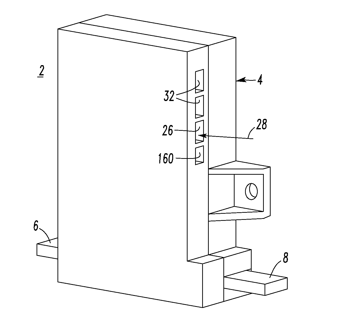
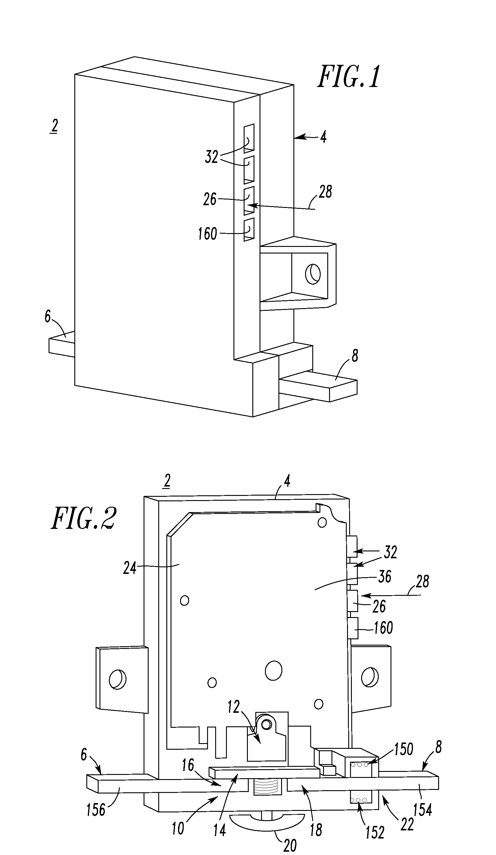
[0033]The example battery disconnect apparatus 2 provides protection to, for example, vehicles (not shown) from electrical fires related to the power available from a vehicle battery (e.g. 30 of FIGS. 3 and 4). The battery disconnect apparatus 2 also serves as the primary on / off disconnect for such vehicles. Preferably, the apparatus 2 includes a number of suitable interfaces 32 (e.g., without limitation, a number of communication interfaces and / or discrete digital I / O) to provide connection points to a vehicle control system (not shown) and / or an external display / control unit (not shown). The circuit 24 as will be described provides suitable fault protection (e.g., without limitation, circuit breaker protection; short circuit; overload; parallel arc fault; series arc fault) for a vehicle battery power circuit (e.g., 34 as shown in FIGS. 3 and 4).

example 2

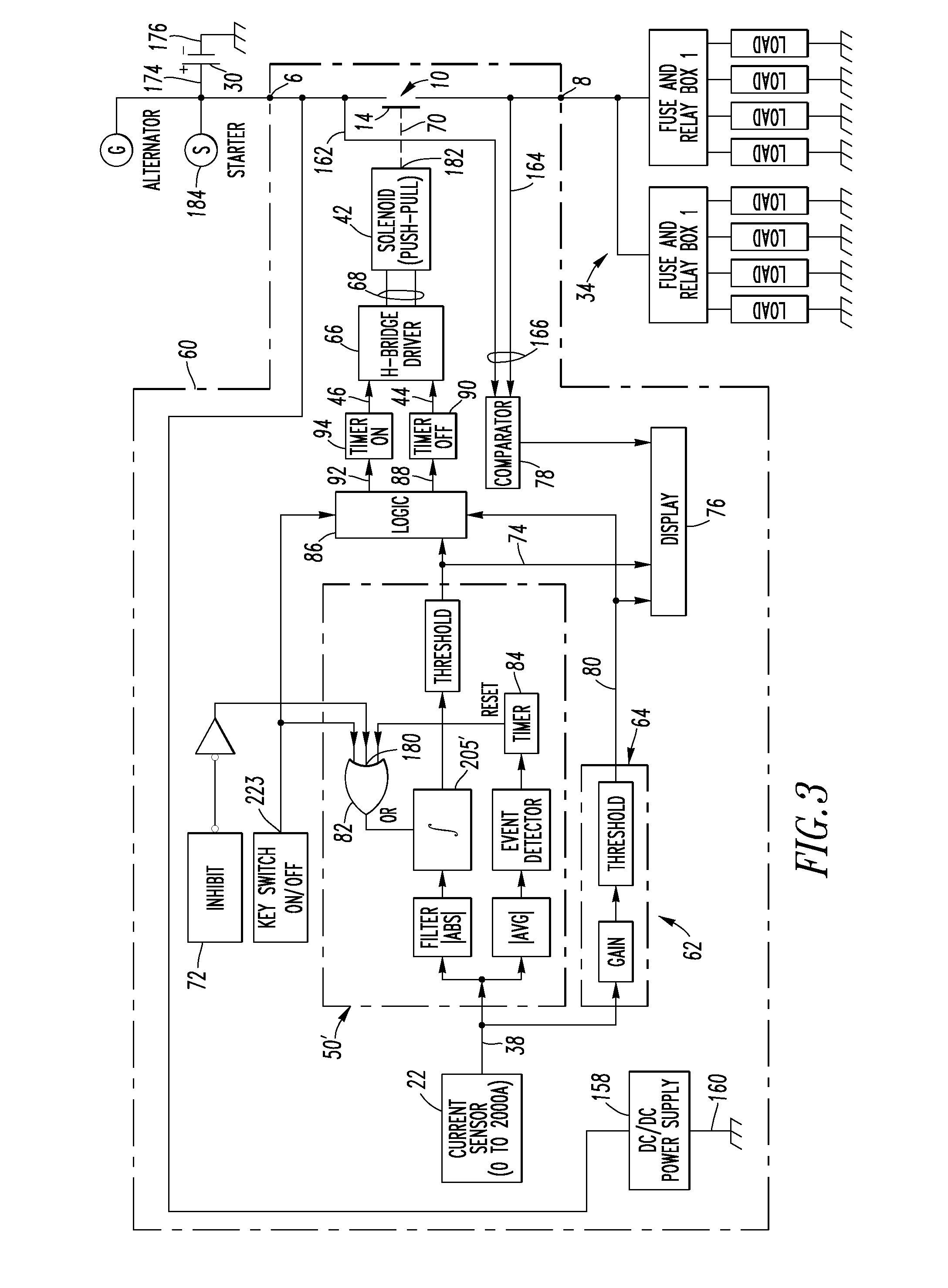
[0034]The example circuit 24 includes a controller printed circuit board 36 that receives a sensed current signal (e.g., 38 of FIGS. 3 and 4) from the current sensor 22 and controls a latching solenoid (e.g., 42 of FIG. 3) of the operating mechanism 12 through an off pulse (e.g., 44 of FIG. 3) to trip open in response to detection of an arc fault, an overload condition or a short circuit condition. The controller printed circuit board 36 also controls the latching solenoid through the off pulse to open in response to the off state of the remote on / off signal 28, and controls the latching solenoid through an on pulse (e.g., 46 of FIG. 3) to close in response to the on state of such remote on / off signal.

example 3

[0035]The example manual operator 20 is a manual palm button (e.g., without limitation, push-off / pull-on mushroom button) employed to manually open and close the separable contacts 10 and override on and off pulses (e.g., 44,46 of FIG. 3; 48 of FIG. 4) from the circuit 24 to the solenoid (e.g., 42 of FIG. 3) of the operating mechanism 12. In this context, the term “override” means that the contactor 70 (FIGS. 3 and 4) will be forced into the other position (e.g., on or off; a position that is different from the position that is requested by the analog or digital electronics of FIGS. 3 and 4). Here, the analog or digital electronics knows about this position because the voltages before and after the movable contact 14 are measured through the conductors 162,164. For example, the contactor 70 may be turned off manually and then turned on electronically, or the contactor 70 may be turned on manually and then turned off electronically.


PUM


Abstract

A battery disconnect includes a housing, battery and load terminals, separable contacts electrically connected between the battery and load terminals, an operating mechanism structured to open and close the contacts, and a manual operator cooperating with the operating mechanism to open and close the contacts. A current sensor is structured to sense current flowing between the battery and load terminals. A circuit cooperates with the current sensor and the operating mechanism to trip open the contacts responsive to arc fault, overload and short circuit conditions associated with the sensed current. The circuit includes a first input structured to receive a remote on / off signal and a second input structured to receive an inhibit signal. The circuit cooperates with the operating mechanism to open and close the contacts responsive to the on / off signal, and to inhibit detection of the arc fault, overload and short circuit conditions responsive to the inhibit signal.

Description

Field of the Invention[0001]This invention pertains generally to circuit interrupters and, more particularly, to direct current or battery disconnect apparatus.BACKGROUND INFORMATION[0002]Known technology provides minimal protection for the electrical power circuit of a vehicle. For example, some vehicles, such as trucks or cars, use fuses. Recently, some automotive vehicles employ fuses and a relay disconnect that opens in the event of a crash.[0003]Direct current (DC) disconnecting switches are known to provide a rapid mechanism to disconnect batteries or other DC power supplies in the event of serious electrical faults. For example, battery disconnect devices (BDDs) help protect and provide disconnection for both 14 VDC and 42 VDC systems. For example, a Delphi® BDD helps provide post-collision circuit protection for electrical cables connected to the battery. A base-level BDD is a low-cost, battery cable circuit protection device that responds during a significant collision. The...

Claims


Application Information

Patent Timeline
Patent Type & Authority Applications(United States)
IPC IPC(8): H01H83/20H02H7/18
CPCH02H7/18
Inventor HASTINGS, JEROME K.PAHL, BIRGERGLOWINSKA, SUSAN A.SOLVESON, MARK G.SCHMALZ, STEVEN C.SUMARA, JAMES R.LEE, DAVIN R.JONES, GILBERT G.DUNNE, JOHN E.
Owner EATON INTELLIGENT POWER LTD
Why Eureka
Try Eureka