Angle Rod Screen Design

a technology of angled rods and rods, applied in the direction of filtration separation, well accessories, separation processes, etc., can solve the problems of cleaning and maintenance problems, adversely affecting the distribution of fluid flow through the reactor, etc., to facilitate cleaning and maintenance, and facilitate the removal of fines, the effect of reducing the pressure drop along the screen

Inactive Publication Date: 2008-06-19
UOP LLC
View PDF8 Cites 16 Cited by
  • Summary
  • Abstract
  • Description
  • Claims
  • Application Information

AI Technical Summary

Benefits of technology

[0005]The invention is a screen assembly for distributing a flow stream to flow substantially uniformly through the screen. The screen assembly further is designed for producing a lower pressure drop along the screen and for facilitating cleaning the screen. The screen assembly includes a plurality of wires spaced apart in a substantially parallel orientation and mounted to a support to maintain the wire spacing, where the spaces between the wires define slots that permit the passage of a fluid. The screen assembly further includes a plurality of angled rods that form the support for the wires. The angled rods have a generally L shaped configuration and where one edge of the L shape is affixed to the wires in a substantially perpendicular orientation. The angled rods form partially covered channels for fluid to distribute and flow through the wire screen. The second edge of the L shape is spaced from a neighboring angled rod to form a gap. The gap is sized to be greater than the space between the wires and facilitates the removal of fines that can accumulate in the partially covered channels.

Problems solved by technology

The horizontal support rods increase the pressure drop by presenting projections that interfere with the flow of fluid into the reactor.
An increase in pressure drop along the axial direction of the reactor on the fluid side produces a non-uniform distribution of the flow of fluid and adversely affects the distribution of fluid flow through the reactor.
However, this design while addressing the pressure drop problem associated with use in a radial flow reactor creates a cleaning and maintenance problem.

Method used


Image

  • Angle Rod Screen Design
  • Angle Rod Screen Design
  • Angle Rod Screen Design

Examples


Embodiment Construction

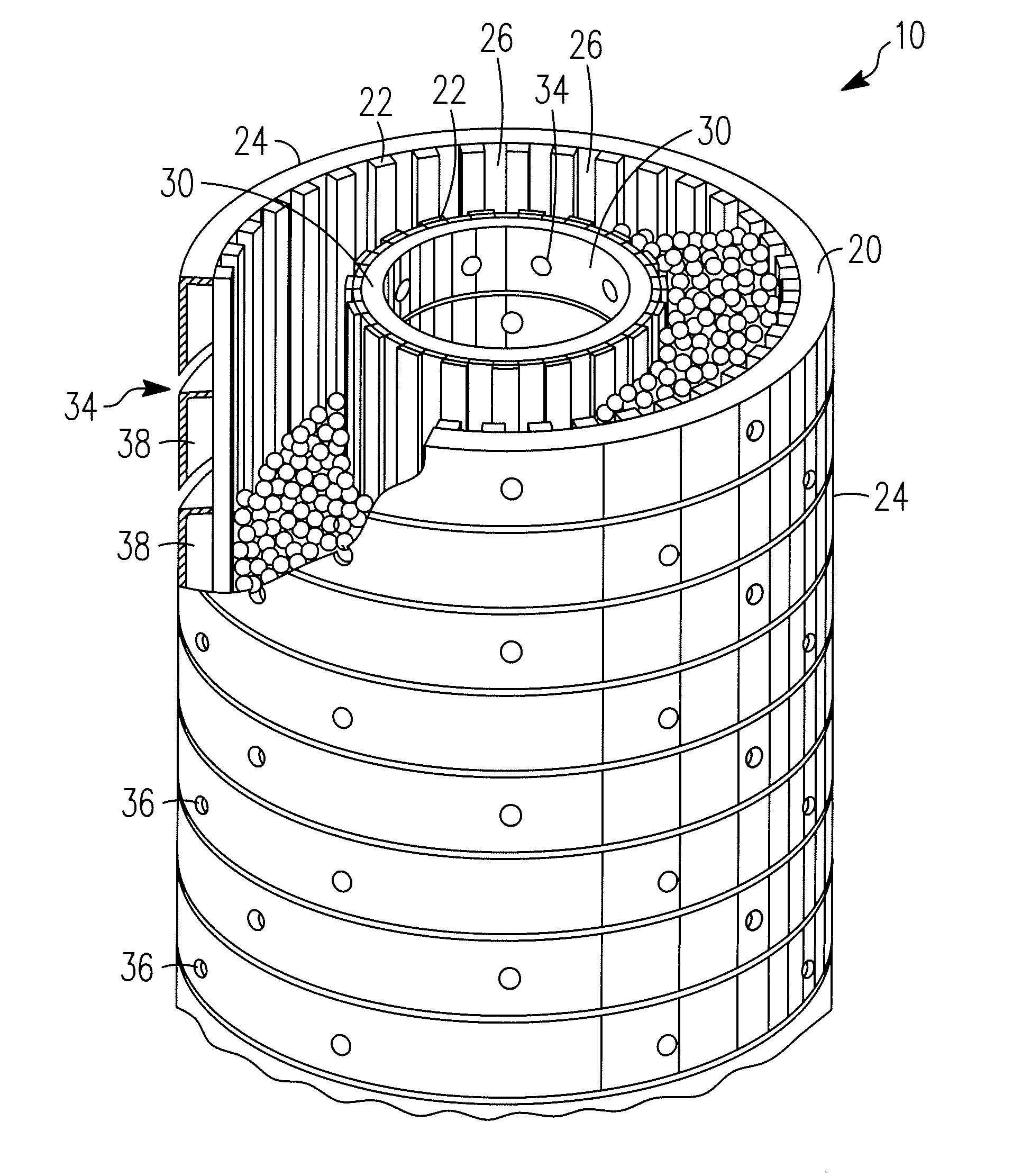
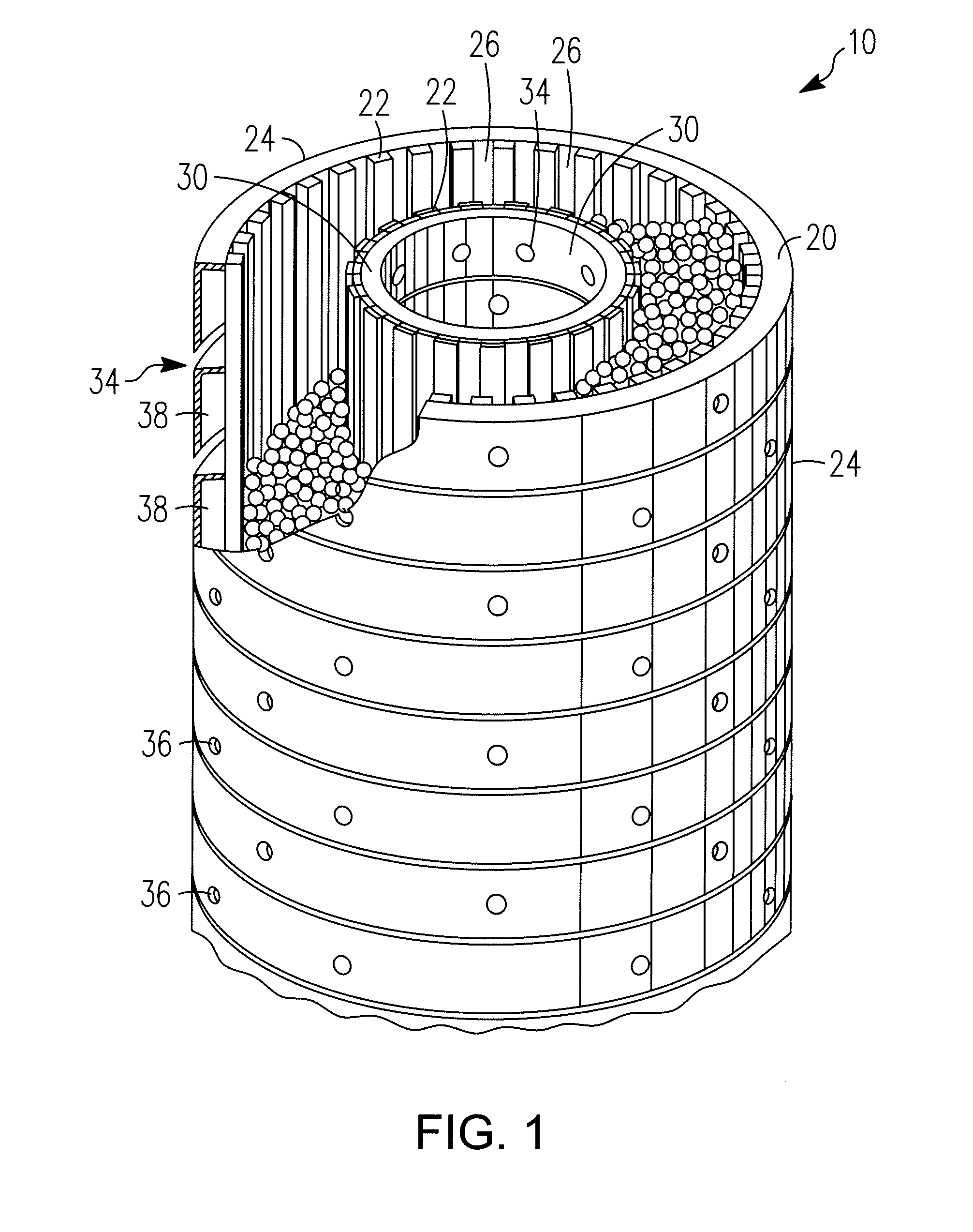
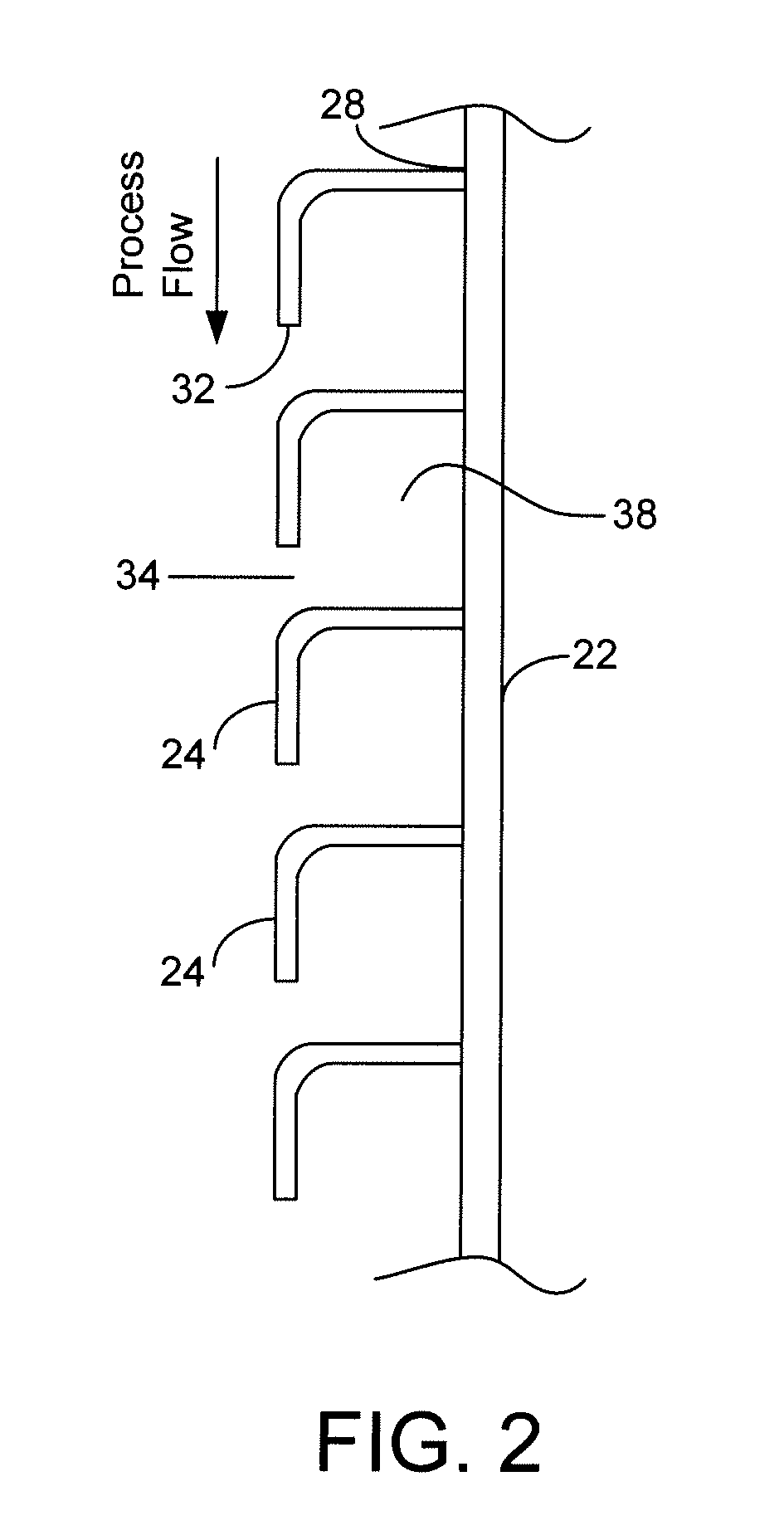
[0009]A wire screen reactor is a reactor where the screen is a series of parallel wires having a substantially uniform spacing between the wires and sufficiently small such that catalyst particles cannot pass through the spacing. The wires are disposed in a parallel and vertical orientation in the reactor, and catalyst can flow in the direction of wires in the wire screen. The wires are affixed, usually by welding, to support rods that maintain the spacing between the wires. The wires are usually shaped to provide for sufficient rigidity to prevent the wires from bending and thereby maintaining the spacing between the wires. An example of a conventional wire screen can be seen in U.S. Pat. No. 2,046,458 and U.S. Pat. No. 4,276,265 which are incorporated by reference in their entirety.

[0010]A problem exists during the operation of a reactor using screens. A catalyst, or an adsorbent, generates fines and the fines penetrate the screen. In a cross-flow reactor with channels surrounding...


PUM

PropertyMeasurementUnit
sizeaaaaaaaaaa
sizeaaaaaaaaaa
areaaaaaaaaaaa

Abstract

A screen for use in distributing a fluid in a process flow system. The screen provides support, and provides for the ability to clean particulates from the screen. The screen includes profiled wires affixed to a support, where the support provides channels to distribute the fluid over the screen. The support includes spacing to improve the cleaning of particulates from the screen.

Description

FIELD OF THE INVENTION[0001]This invention relates to screens for the distribution of a fluid in a process flow stream application. In particular, this invention relates to reducing the pressure drop, and providing a design for improved flow and to remove particulates accumulated at the screen.BACKGROUND OF THE INVENTION[0002]Currently, wire screen supports for radial flow reactors use horizontal support rods. The horizontal support rods increase the pressure drop by presenting projections that interfere with the flow of fluid into the reactor. The design of screens for use in radial flow reactors is for a sufficient pressure drop to provide a uniform distribution of the flow of fluid through the reactor. A conventional well screen with profiled wires can be found in U.S. Pat. No. 2,046,458. The wires are helically wrapped around a plurality of longitudinal rods, and welded to the rods to define slots of predetermined widths. After the wires are welded to the rods to form the screen...

Claims


Application Information

Patent Timeline
Patent Type & Authority Applications(United States)
IPC IPC(8): B01D39/10B01J19/00
CPCB01D46/0024B01D46/0043B01J2208/00884B01J8/008B01J8/0214B01D46/40B01D46/64
Inventor KOVES, WILLIAM J.
Owner UOP LLC
Why Eureka
Try Eureka