Method of data encoding, compression, and transmission enabling maskless lithography

a maskless lithography and data compression technology, applied in the field of data encoding, compression and transmission enabling maskless lithography, can solve the problems of inability to consider electron beam (e-beam) lithography as an efficient mass method, inability to meet the requirements of e-beam writers,

Inactive Publication Date: 2008-06-19
KLA TENCOR TECH CORP
View PDF2 Cites 22 Cited by
  • Summary
  • Abstract
  • Description
  • Claims
  • Application Information

AI Technical Summary

Benefits of technology

The present invention relates to improving directed writing by charging particles for use in semiconductor device fabrication. This includes developing new techniques and equipment that enhance this process.

Problems solved by technology

The technical problem addressed in this patent is how to efficiently use e-beam lithography technology for mass production of wafers without being limited by the speed of older machines. There is also a challenge of handling the large amount of data required for individual elements of the machine when creating complex patterns. A solution needs to provide faster and reliable processing and applications of pattern data.

Method used


Image

  • Method of data encoding, compression, and transmission enabling maskless lithography
  • Method of data encoding, compression, and transmission enabling maskless lithography
  • Method of data encoding, compression, and transmission enabling maskless lithography

Examples


Embodiment Construction

[0027]Aspects of the present invention are particularly shown and described with respect to certain embodiments and specific features thereof. The inventors point out that the embodiments set forth herein below are to be taken as illustrative rather than limiting. It should be readily apparent to those of ordinary skill in the art that various changes and modifications in form and detail may be made without departing from the spirit and scope of the invention.

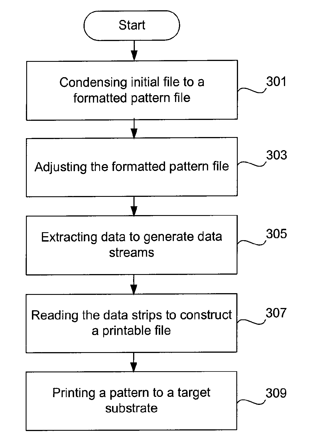
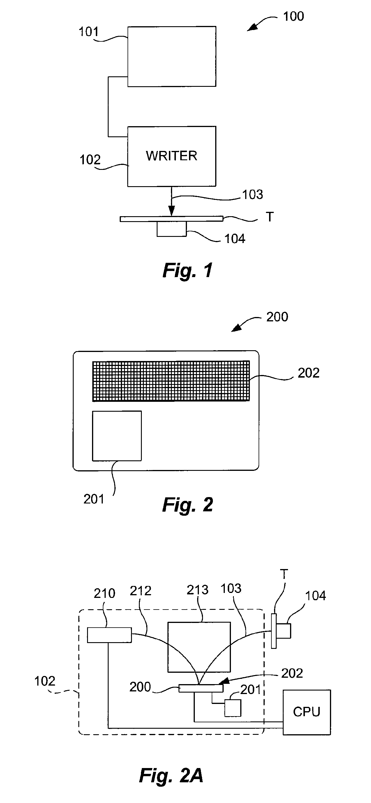
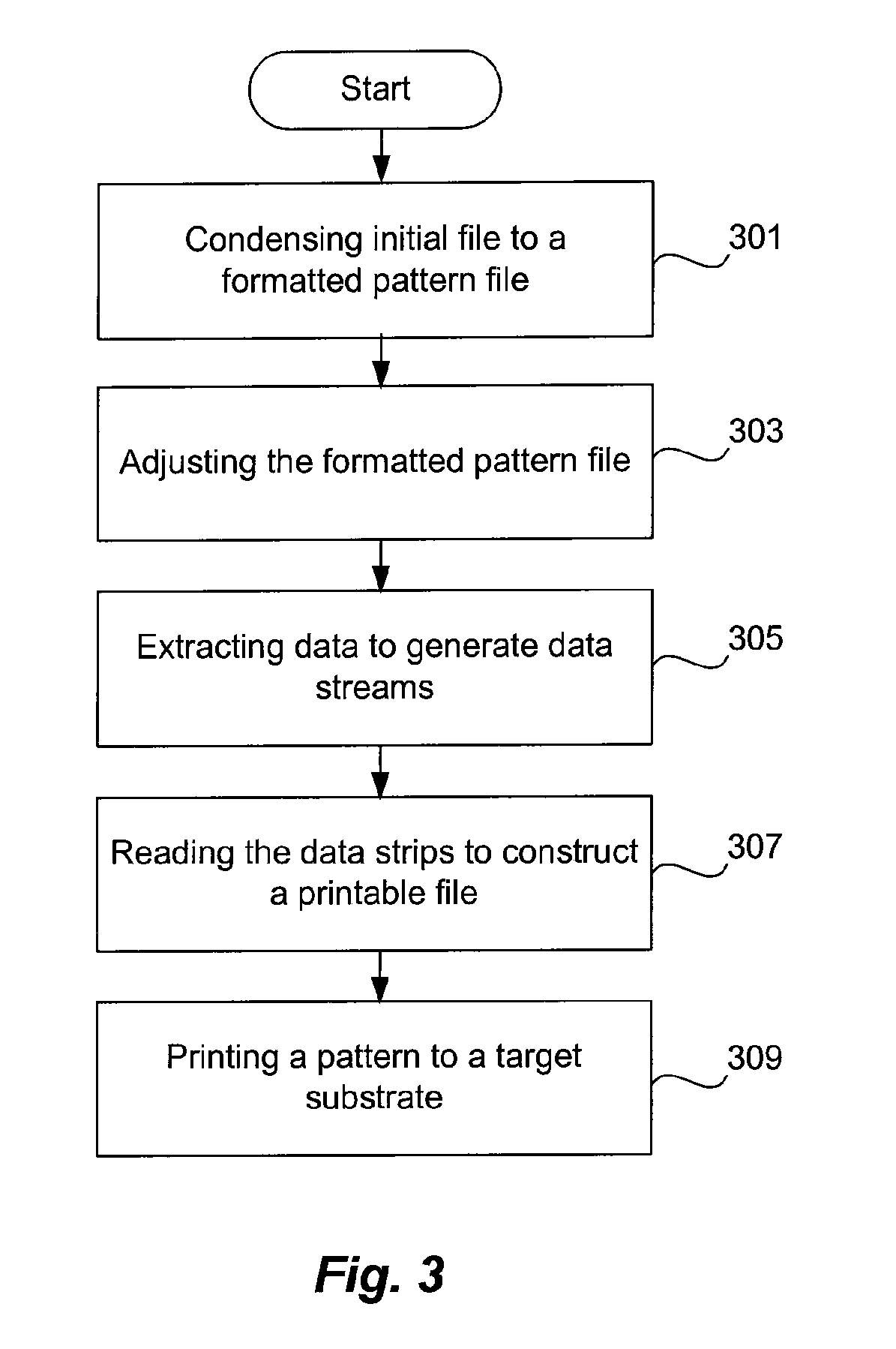
[0028]The following detailed description describes various methodologies and embodiments that can be employed to transfer a pattern on to a substrate using a direct write process with a patterned charged-particle beam. In general, the present invention encompasses charged-particle beam direct write lithography apparatus and methods for their use in generating patterned targets which can include, but are not limited to, semiconductor wafers and masks, as well as other surfaces capable of pattern transfer with a charged-particle ...


PUM


Abstract

A method and tool for conducting charged-particle beam direct write lithography is disclosed. A disclosed method involves condensing an initial design file down to a set of profiles and a pattern of relative locations to form a formatted pattern file. The formatted pattern file is adjusted to accommodate desired pattern corrections. Portions of the formatted pattern records are extracted to form data strips that have a plurality of channels with a pattern of profiles and spatial indicators. Data strips are sequentially read to construct a printable pattern of profiles and spatial indicators that specify the locations of the profiles. Additionally, the pattern of profiles are sequentially printed from each data strip onto a substrate to form the desired pattern on the substrate.

Description


Claims


Application Information

Patent Timeline
Owner KLA TENCOR TECH CORP
Why Eureka
Try Eureka