Apparatus and method for frequency shifting of a wireless signal and systems using frequency shifting

a wireless signal and antenna technology, applied in the field of frequency shifting of wireless signals, can solve the problems of increased complexity, physical large enclosure, high cost, etc., and achieve the effect of increasing the reach and distance between the two wireless units, increasing the coverage, and increasing the coverag

Active Publication Date: 2008-06-19
CORNING OPTICAL COMM WIRELESS
View PDF8 Cites 72 Cited by
  • Summary
  • Abstract
  • Description
  • Claims
  • Application Information

AI Technical Summary

Benefits of technology

[0053]In another aspect of the present invention, frequency shifting is used in a wireless network for increasing the coverage and seamlessly bridging between two isolated or separated wireless coverage areas. The network is based on two frequency shifters, communicating with each other over a first frequency band. Wireless signal from a first wireless unit is received by one shifter and then frequency shifted to another frequency band, and transmitted to the other shifter. The other shifter shifts the received signal to the original transmitted frequency band and transmits to another wireless unit, being distant from the first wireless unit, thus creating a wireless link between the two wireless units. The other direction is also operative for allowing half-duplex or bi-directional operation.
[0054]The communication between the frequency shifters above may also use two additional intermediate frequency shifters (or more), thus having additional frequency shifting to another distinct frequency band, allowing or additional increased reach and distance between the two wireless units.
[0055]In another aspect of the present invention, frequency shifting is used in a wireless network for increasing the coverage and seamlessly bridging between two or more isolated or separated wireless coverage areas using an interconnecting wired medium. The network is based on two or more frequency shifters, each covering a distinct area, communicating with each other over the wired medium. Wireless signal from a first wireless unit is received by one shifter and then down frequency shifted for being carried over the wired medium, and transmitted to the other shifter. The other shifter shifts the received signal to the original transmitted frequency band and transmits to another wireless unit, being distant from the first wireless unit, thus creating a wireless link between the two wireless units. The other direction is also operative for allowing half-duplex or bi-directional operation.
[0056]Connecting the frequency shifters to the wired medium may make use of a suitable connector, as well as a protection circuitry for accommodating transients, over-voltage and lightning, and any other protection means for reducing or eliminating the damage from an unwanted signal over the wired medium. A band pass filter may also be used for passing only the shifted wireless signals, and rejecting or stopping other signals in the described path. A transformer may be used for isolating and reducing common-mode interferences. Further a wiring driver and wiring receivers may be used in order to transmit and receive the appropriate level of signal to and from the wired medium. Equalizer may also be used in order to compensate for any frequency dependent characteristics of the wired medium.

Problems solved by technology

Such implementation commonly has a high part count, leading to high cost, a physically large enclosure, added complexity, lower reliability and other disadvantages.
The communication channel in wireless environments imposes various impairments, such as attenuation, fading, multi-path, interferences, and many other impairments.
As such, in most cases a single wireless unit (such as an access point) cannot efficiently cover the whole premises.
As explained above, installing a dedicated network wiring infrastructure in existing houses is not practical.
There are several drawbacks to using powerlines as a backbone for connecting WLAN units involves several drawbacks.
The type of wiring, noise, and the general hostile environment results in a poor and unreliable communication medium, providing low data rates and requiring complex and expensive modems.
As such, this solution is complex, expensive and offers low reliability due to the amount of hardware required.

Method used


Image

  • Apparatus and method for frequency shifting of a wireless signal and systems using frequency shifting
  • Apparatus and method for frequency shifting of a wireless signal and systems using frequency shifting
  • Apparatus and method for frequency shifting of a wireless signal and systems using frequency shifting

Examples


Embodiment Construction

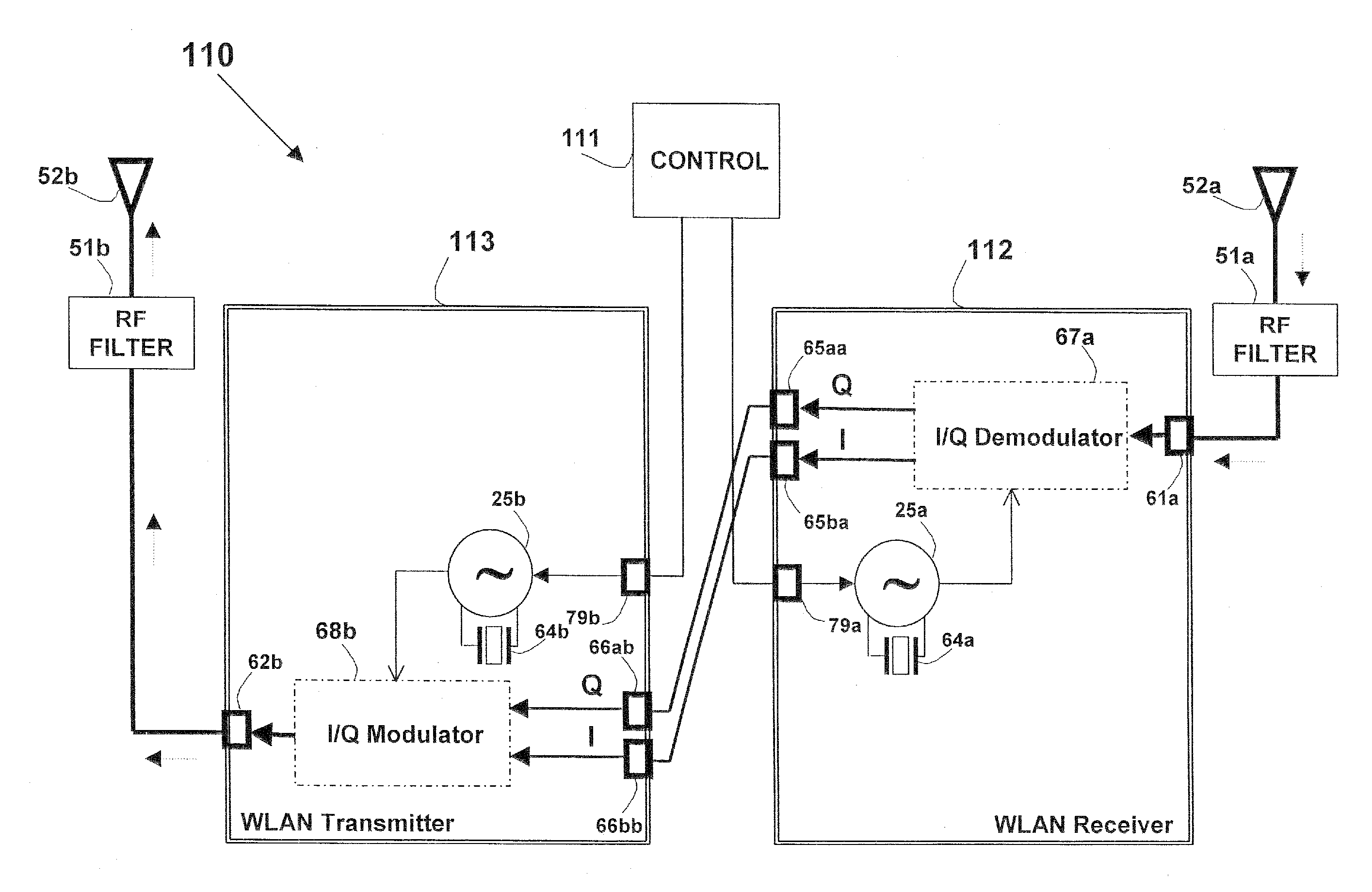
[0150]The principles and operation of a network according to the present invention may be understood with reference to the figures and the accompanying description wherein similar components appearing in different figures are denoted by identical reference numerals. The drawings and descriptions are conceptual only. In actual practice, a single component can implement one or more functions; alternatively, each function can be implemented by a plurality of components and circuits. In the figures and descriptions, identical reference numerals indicate those components that are common to different embodiments or configurations. Identical numerical references (even in the case of using different suffix, such as 45a, 45b and 45c) refer to functions or actual devices which are either identical, substantially similar or having similar functionality). It will be readily understood that the components of the present invention, as generally described and illustrated in the figures herein, cou...


PUM


Abstract

Systems, methods and apparatus for improving the coverage of a wireless network based on frequency shifting scheme. A wireless signal in a frequency band is shifted to another distinct band, and carried in the shifted band, using wired or wireless mediums to another location, wherein the wireless signal is shifted back to the original frequency band. The frequency shifting may make use of a conventional frequency shifting schemes such as mixer / filter and heterodyne. In one embodiment the wireless signal is frequency shifted by converting it to other representing signals (such as I / Q components) and forming the frequency-shifted signal from the representations. The system is may be used to increase in-door or outdoor coverage, as well as bridging between in-door and outdoor networks. The medium may use dedicated wiring or existing service wiring in a residence or building, including LAN, telephone, AC power and CATV wiring. The system (in whole or in part) may be enclosed as a stand-alone unit, housed in integrated form as part of a service outlet or as a snap-on / plug-in module. Methods and other systems with different advantageous configurations are also described. This abstract is not intended to limit or construe the scope or meaning of the claims.

Description

CROSS-REFERENCE TO RELATED APPLICATION[0001]This is a continuation of application Ser. No. 11 / 329,270, filed Jan. 11, 2006, the disclosure of which is incorporated herein by reference.FIELD OF THE INVENTION[0002]The present invention relates generally to frequency shifting of a signal, and specifically the shifting of wireless signals. More particularly, embodiments of the present invention relate to improving the coverage of wireless networks, using frequency shifted signals over non-wired and wired mediums.REFERENCES[0003]The following documents are incorporated in their entirety for all purposes as if fully set forth herein:[0004]a. U.S. Pat. No. 6,862,353 to Rabenko. et al. entitled: “System and Method for Providing Power over a Home Phone Line Network,”, referred to herein as '353.[0005]b. U.S. Patent Application Publication 2004 / 0151305 to Binder, et al. entitled: “Method and System for Providing DC Power on Local Telephone Lines”, referred to herein as '1305.[0006]c. U.S. Pat...

Claims


Application Information

Patent Timeline
Patent Type & Authority Applications(United States)
IPC IPC(8): H04B7/14
CPCH04B7/15542H04B7/15528H04B7/2606H04L27/32H04L27/10H04W72/0453H04L69/08
Inventor BINDER, YEHUDAHAZANI, AMI
Owner CORNING OPTICAL COMM WIRELESS
Why Eureka
Try Eureka