Grouped leads for spinal stimulation

a spinal cord and grouping technology, applied in the field of spinal cord grouping leads, can solve the problems of uncontrollable amount of stimulation energy needed to provide the desired amount of neurostimulation, unsatisfactory stimulation of the motor nerve, further altering the local neural excitability state, etc., to achieve the effect of reducing deleterious side effects and improving treatment effectiveness

a spinal cord and grouping technology, applied in the field of spinal cord grouping leads, can solve the problems of uncontrollable amount of stimulation energy needed to provide the desired amount of neurostimulation, unsatisfactory stimulation of the motor nerve, further altering the local neural excitability state, etc., to achieve the effect of reducing deleterious side effects and improving treatment effectiveness

US20080147156A1Inactive Publication Date: 2008-06-19ST JUDE MEDICAL LUXEMBOURG HLDG SMI S A R L SJM LUX SMI

Image

  • Grouped leads for spinal stimulation
  • Grouped leads for spinal stimulation
  • Grouped leads for spinal stimulation

Examples


Embodiment Construction

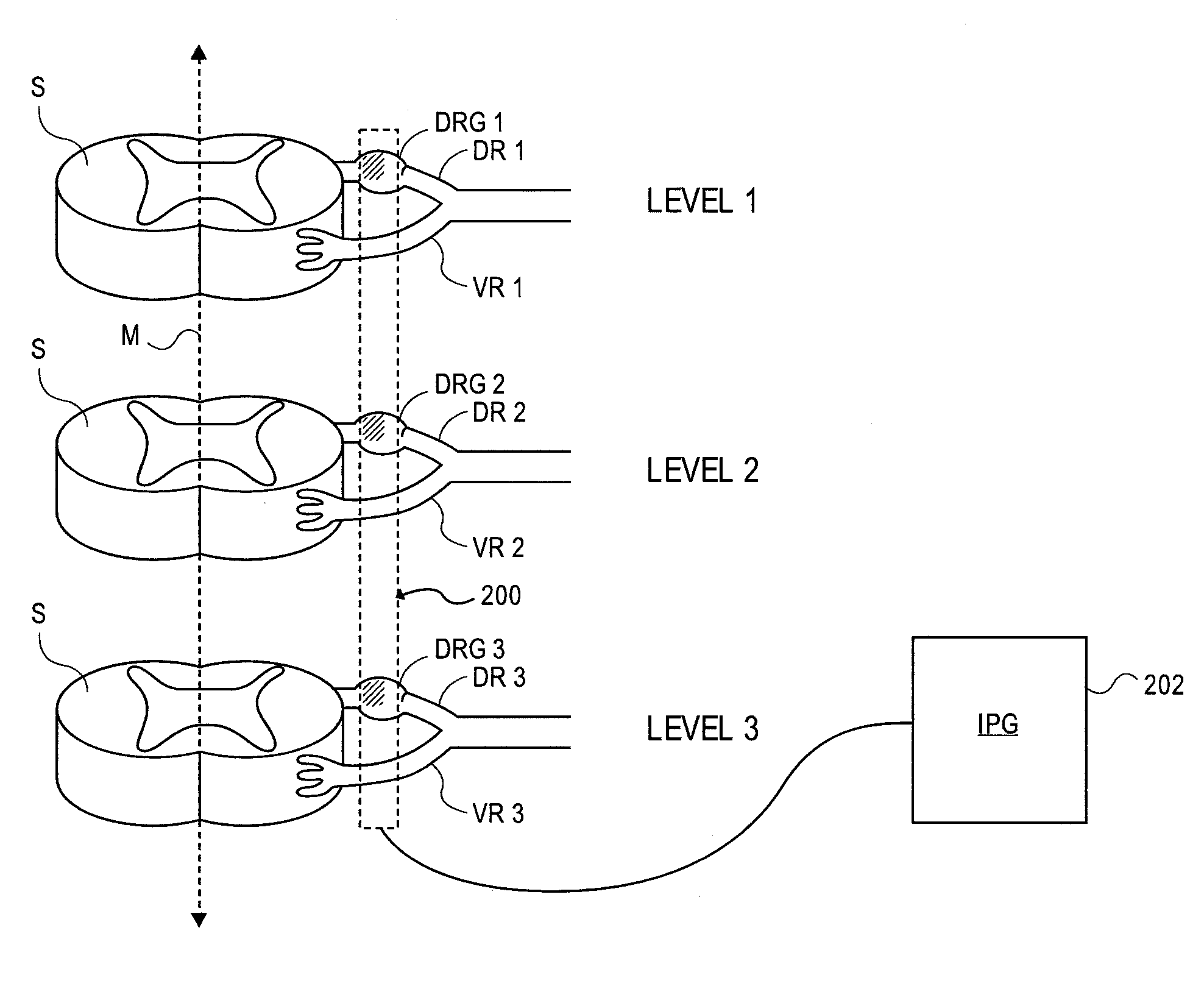
[0041]FIG. 6 illustrates positioning of an embodiment of a device 200 of the present invention so as to optionally simultaneously stimulate various levels (levels 1, 2, 3 in this example) of the spinal cord S. The device 200 is shown positioned within an epidural space of the spinal column at a lateral distance from the midline M of the of the spinal column which aligns the device 200 with the dorsal root ganglions DRG 1, DRG 2, DRG 3. Thus, portions of the device 220 align with and may optionally contact the dorsal root ganglions DRG 1, DRG 2, DRG 3, as indicated by shading. These aligned portions provide targeted or selective stimulation of one or more of the dorsal root ganglions DRG 1, DRG 2, DRG 3 while avoiding or reducing stimulation to surrounding tissues, such as the ventral roots VR1, VR2, VR3.

[0042]The device 200 is electrically connected to a power source or implantable pulse generator (IPG) 202, as shown, which is implanted in the body of the patient. FIG. 6 illustrates...


PUM


Abstract

Devices, systems and methods are provided for simultaneously stimulating the spinal anatomy at various target locations, such as spinal levels, along the spinal cord. In some embodiments, the devices, systems and methods stimulate the various spinal levels at specific nerve anatomies, such as the dorsal root DR or more specifically the dorsal root ganglion DRG. Optionally, the devices, systems and methods may be used to stimulate a single DRG or other anatomies.

Description

CROSS-REFERENCES TO RELATED APPLICATIONS[0001]This application claims priority of provisional patent application No. 60 / 873,464 (Attorney Docket No. 10088-706.101), filed on Dec. 6, 2006, which is incorporated herein by reference for all purposes.STATEMENT AS TO RIGHTS TO INVENTIONS MADE UNDER FEDERALLY SPONSORED RESEARCH AND DEVELOPMENT[0002]NOT APPLICABLEREFERENCE TO A “SEQUENCE LISTING,” A TABLE, OR A COMPUTER PROGRAM LISTING APPENDIX SUBMITTED ON A COMPACT DISK[0003]NOT APPLICABLEBACKGROUND OF THE INVENTION[0004]The application of specific electrical energy to the spinal cord for the purpose of managing pain has been actively practiced since the 1960s. It is known that application of an electrical field to spinal nervous tissue can effectively mask certain types of pain transmitted from regions of the body associated with the stimulated nervous tissue. Such masking is known as paresthesia, a subjective sensation of numbness or tingling in the afflicted bodily regions. Applicatio...

Claims


Application Information

Patent Timeline
19 Jun 2008
Publication
US20080147156A1
IPC
A61N1/05
CPC
A61N1/0553
Inventors
IMRAN, MIR A.