Thermal transfer methods and strucures for microfluidic systems

a technology of microfluidic systems and thermal transfer methods, applied in the direction of positive displacement liquid engines, laboratory glassware, instruments, etc., can solve the problems of fluid transfer between different features of the device, transfer process, potential errors, complex and associated high costs, etc., and achieve the effect of improving efficiency

Active Publication Date: 2008-06-26
DIASORIN ITALIA SPA
View PDF11 Cites 41 Cited by
  • Summary
  • Abstract
  • Description
  • Claims
  • Application Information

AI Technical Summary

Benefits of technology

This patent describes how to use a thermal transfer system to move fluids without affecting their temperature during the movement. By having a separate chamber for driving the motion, the part of the device closest to where the fluids will be affected remains cold or hot enough to maintain a stable pressure on the fluids. This allows for controlled movements with different rates and patterns, making it useful for various applications like cleaning samples or delivering reagents accurately. Additionally, this design works better when moving small stages of fluid because there's less resistance compared to traditional systems.

Problems solved by technology

This patent discusses how to improve the movement of substances inside tiny machines used for medical testing and research. These machines use heat to create suction to move liquids around, eliminating the need for humans to manually handle them. However, current techniques still require some level of control by a user and can be complicated and expensive.

Method used


Image

  • Thermal transfer methods and strucures for microfluidic systems
  • Thermal transfer methods and strucures for microfluidic systems
  • Thermal transfer methods and strucures for microfluidic systems

Examples


Embodiment Construction

[0036]In the following detailed description of exemplary embodiments of the invention, reference is made to the accompanying figures of the drawing which form a part hereof, and in which are shown, by way of illustration, specific embodiments in which the invention may be practiced. It is to be understood that other embodiments may be utilized and structural changes may be made without departing from the scope of the present invention.

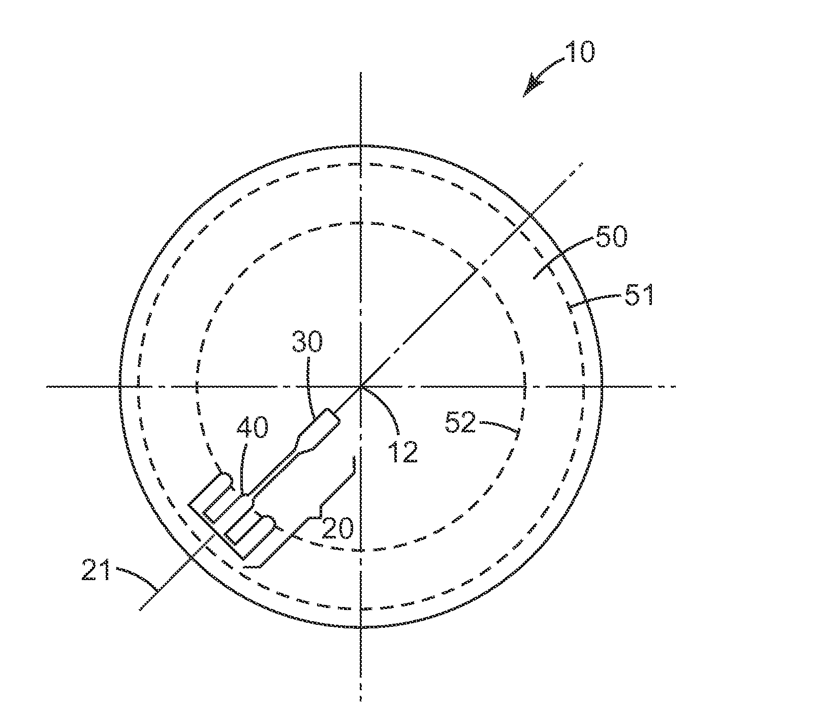
[0037]The present invention provides a processing device that can be used in the processing of an analyte. The analyte itself may be in the form of a fluid (e.g., a solution, etc.), or the analyte may be in the form of a solid or semi-solid material carried in a fluid. The analyte may be entrained in the fluid, in solution within the fluid, etc. For simplicity, the term “analyte” will be used herein to refer to any fluid in which the analyte is or may be located—regardless of whether the analyte is, itself, a fluid or is contained within a carrier flui...


PUM


Abstract

Processing devices that include one or more process arrays with thermal transfer structures that can be used alone or in conjunction with gravity/rotation to transport fluids within a microfluidic system. The thermal transport function can be accomplished by changing the temperature of one or more chambers to create a vacuum to draw fluids in selected directions within the process array. The methods and apparatus of the present invention may provide the ability to move fluids in a direction that is against the direction of gravity or any centrifugal forces generated by rotating a processing device using the thermal transfer structures. In other words, fluids may be moved against the direction of gravity or towards the axis of rotation using the thermally-activated vacuum.

Description


Claims


Application Information

Patent Timeline
Owner DIASORIN ITALIA SPA
Why Eureka
Try Eureka