Spray type heat exchange device

a heat exchange device and spray type technology, applied in indirect heat exchangers, milk preservation, lighting and heating apparatus, etc., can solve the problems of large amount of liquid refrigerant required, difficult to enter liquid refrigerant into the inlet of the compressor, increased power consumption of the compressor, etc., to maximize space utilization, maximize the number of heat exchange tubes, and maximize the effect of space utilization

Inactive Publication Date: 2008-06-26
IND TECH RES INST
View PDF12 Cites 79 Cited by
  • Summary
  • Abstract
  • Description
  • Claims
  • Application Information

AI Technical Summary

Benefits of technology

[0022]In a preferred embodiment, adjacent upper and lower columns of heat transfer tubes are alternately arranged such that refrigerant flowing through an upper column of heat transfer tubes and dripping down can pass through spacing of a lower column of heat transfer tubes and drip down to a next lower column of heat transfer tubes, thereby maximizing the space usage and disposing heat transfer tubes more efficiently.
[0023]In a embodiment, the spray unit is disposed at a position such that distance from spray surface of the spray unit to lower side of the top portion of the shell is 5% to 25% of the inner diameter of the shell, and the distributing unit is disposed at a position such that distance from surface of the distributing unit to lower side of the top portion of the shell is 40% of the inner diameter of the shell, thereby maximizing the number of heat transfer tubes disposed inside the heat exchange device. Out of this embodiment, the other portions could be applied in realizing this invention.
[0024]In another embodiment, the spray unit is disposed at a position such that distance from spray surface of the spray unit to lower side of the top portion of the shell is 5% to 25% of the inner diameter of the shell, the distributing unit between the first and second group sets of heat transfer tubes is disposed at a position such that distance from surface of the distributing unit to lower side of the top portion of the shell is 20% to 30% of the inner diameter of the shell, and the distributing unit between the second and third group sets of heat transfer tubes is disposed at a position such that distance from surface of the distributing unit to lower side of the top portion of the shell is 45% to 50% of the inner diameter of the shell, thus maximizing the number of heat transfer tubes disposed inside the heat exchange device. Out of this embodiment, the other portions could be applied in realizing this invention.

Problems solved by technology

However, to prevent liquid refrigerant that is not completely evaporated from being absorbed into compressor and damaging compressor, the refrigerant flows into the compressor that needs to be overheated and causes the power consumption of the compressor increased.
The liquid refrigerant is not easy to enter into the inlet of the compressor in this type of evaporator.
However, since tubes of the flooded type evaporator need to be immersed in liquid refrigerant in the shell side of the flooded type evaporator, a great deal of liquid refrigerant is required.
Quantity of the refrigerant filled in the flooded type evaporator might be over two times that of the refrigerant filled in the direct expansion type evaporator, which accordingly increases the cost and increases environment burden.
Accordingly, to reach expected heat exchange efficiency, shell size of the evaporator needs to be increased, which consumes space, increases the cost of material and fabrication.

Method used


Image

  • Spray type heat exchange device
  • Spray type heat exchange device
  • Spray type heat exchange device

Examples


first embodiment

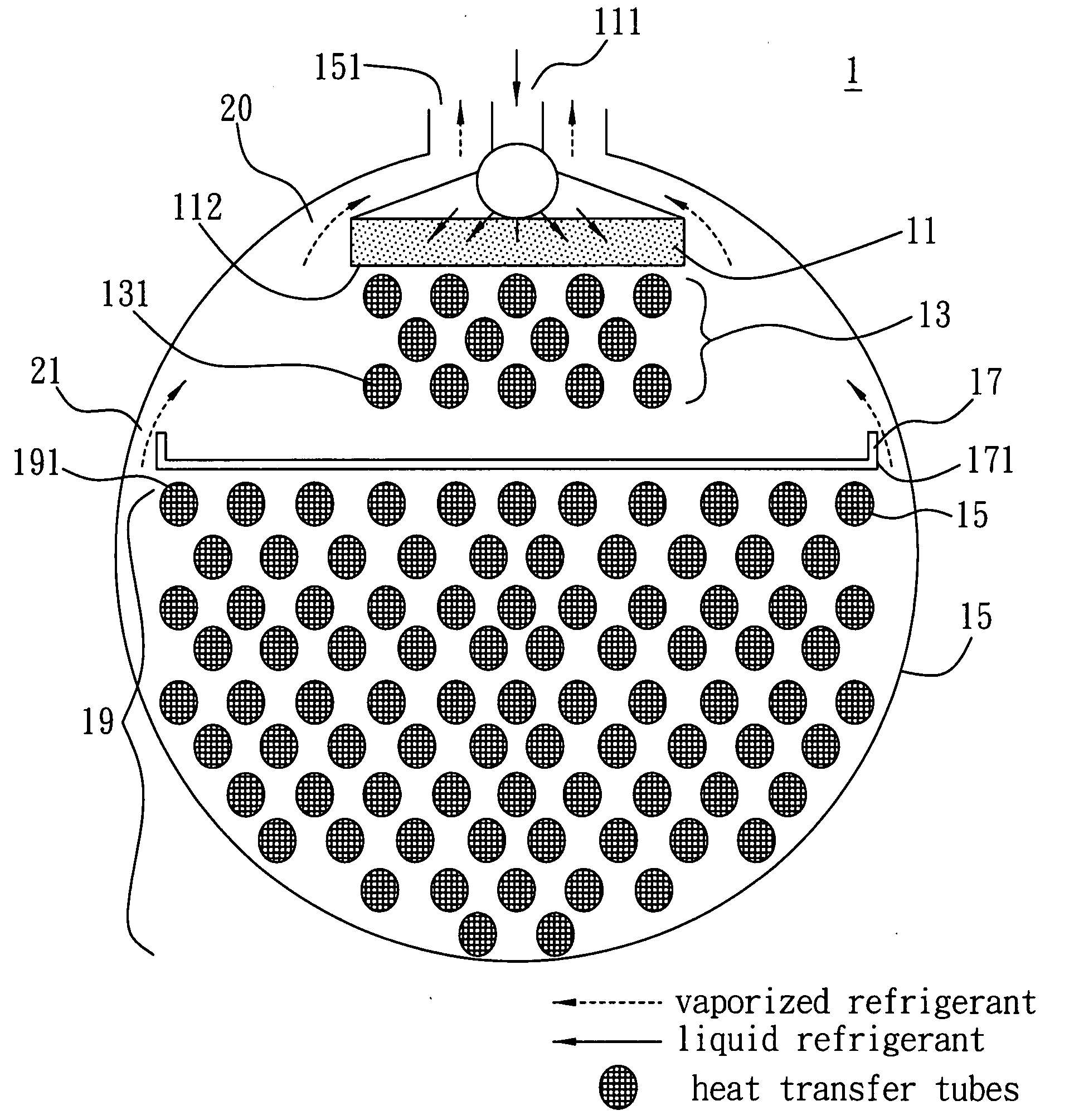
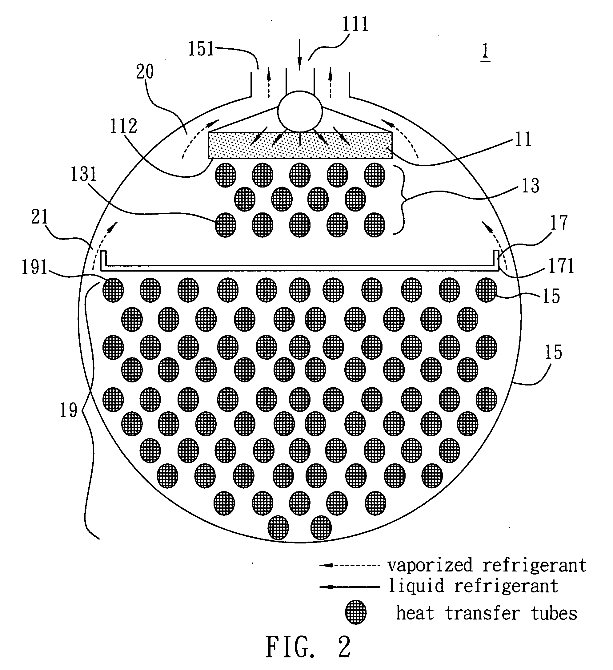
[0031]FIG. 2 is a sectional diagram of a spray type heat exchange device 1 the present invention. As shown in FIG. 2, the spray type heat exchange device 1 has a shell 15. Inside the shell 15 there are disposed sequentially, a spray unit 11, a first group set of heat transfer tubes 13, a distributing unit 17, and a second group set of heat transfer tubes 19.

[0032]The spray unit 11 has an inlet 111 connected with a refrigerant supply source (not shown), and a spray surface 112 having a plurality of dripping holes or dripping slots (not shown) disposed thereon for allowing the refrigerant to drip downward. There are no special limits on size, shape and distribution of the dripping holes or dripping slots, as long as liquid refrigerant can be uniformly dripped through the whole spray surface 112 in coordinate with supply of the refrigerant. The dripping holes or slots are preferably located at a position corresponding to the heat transfer tubes such that refrigerant dripped from the d...

second embodiment

[0042]FIG. 3 is a sectional diagram of a spray type heat exchange device according to the present invention. As shown in FIG. 3, besides a spray unit 11, a first group set of heat transfer tubes 13, two distributing units 17-1, 17-2, and a second group set of heat transfer tubes 19 that are disposed sequentially in shell 15 of a spray type heat exchange device 2, the spray type heat exchange device 2 has another distributing unit 23 and a third group set of heat transfer tubes 25 disposed below the second group set of heat transfer tubes 19.

[0043]The distributing unit 23 has a nearly opened rectangular section and in the shape of a shallow plate. The distributing unit 23 also has a plurality of dripping holes and / or dripping slots disposed on a whole surface 231 thereof. Similarly, there are no special limits on size, shape and distribution of the dripping holes or slots, as long as the liquid refrigerant can uniformly drip through the surface 231 in combination with supply of refri...


PUM


Abstract

A spray type heat exchange device includes a spray unit, a first group set of heat transfer tubes, at least a distributing unit and a second group set of heat transfer tubes. The distributing unit redistributes the remaining liquid refrigerant that is sprayed out from the spray unit and flowed through the first group set of heat transfer tubes, and the remaining liquid refrigerant is dropped downwardly to the second group set of heat transfer tubes. By this disclosed method, the inner space of the heat exchange device could be fully utilized to configure and accommodate more heat transfer tubes therein.

Description

BACKGROUND OF THE INVENTION[0001]1. Field of the Invention[0002]The present invention relates generally to a heat exchange device applicable in a chiller system, and more particularly, a spray type heat exchange device that the liquid refrigerant flows from upward to downward.[0003]2. Description of Related Art[0004]A conventional cooling system mainly comprises four components: compressor, expansion device, evaporator and condenser. Therein, the evaporator is implemented by making low temperature liquid refrigerant contact the surface of heat transfer tubes with high temperature object fluid flowing therein and remove heat from the surface, thereby cooling the fluid. Currently, for concerning the environmental protection and cost saving, it is a criterion of decreasing the filled refrigerant inside the cooling system without decreasing heat exchange efficiency.[0005]Many improvements have been made on evaporator of the cooling system in recent years. There are three types of evapor...

Claims


Application Information

Patent Timeline
Patent Type & Authority Applications(United States)
IPC IPC(8): F25B39/02
CPCF25B39/028F25B2339/0242F25B2500/01F28F9/0265F28D3/04F28D7/163F28D3/02
Inventor LIU, CHIA-HUNGLIU, CHUNG-CHE
Owner IND TECH RES INST
Why Eureka
Try Eureka