Tube spacer, method of manufacturing the same, and heat exchanger

a technology of spacers and tubes, applied in the field of tube spacers, can solve the problems of difficult operation, inability to support the heat transfer tube, and difficult insertion,

Active Publication Date: 2008-06-26
NORITZ CORP
View PDF6 Cites 9 Cited by
  • Summary
  • Abstract
  • Description
  • Claims
  • Application Information

AI Technical Summary

Benefits of technology

[0010]An object of the present invention is to solve or lesse

Problems solved by technology

However, the above-described conventional structure has the following problems.
As a result, such insertion is not easy.
Although it is convenient that the tube spacer 9A can be inserted from one side of the heat transfer tubes

Method used


Image

  • Tube spacer, method of manufacturing the same, and heat exchanger
  • Tube spacer, method of manufacturing the same, and heat exchanger
  • Tube spacer, method of manufacturing the same, and heat exchanger

Examples


Embodiment Construction

[0036]Preferred embodiments of the present invention will be described below in detail with reference to the accompanying drawings.

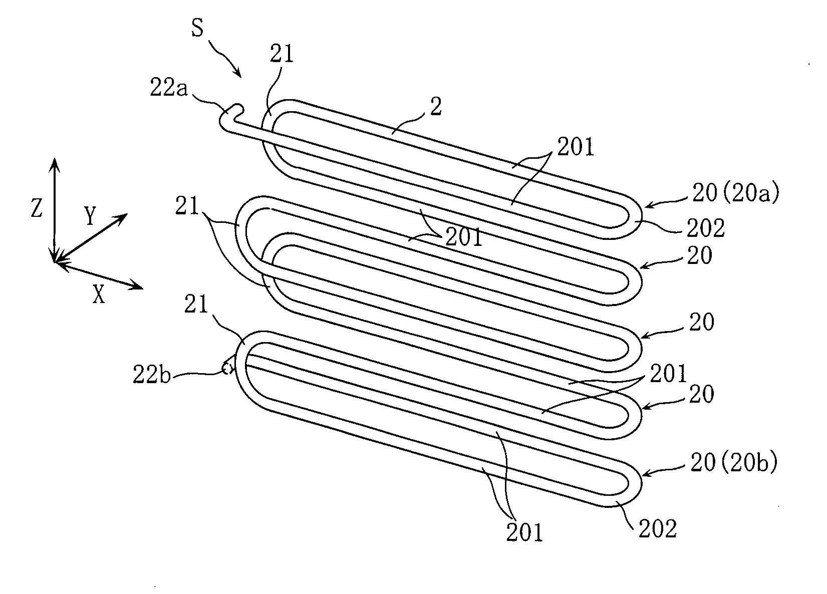
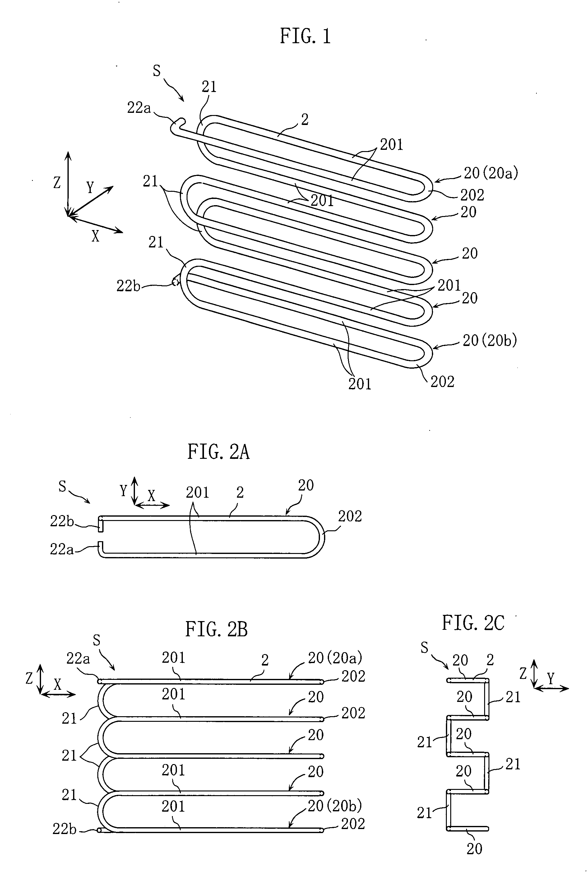
[0037]FIG. 1 and FIGS. 2A to 2C show an example of tube spacer according to the present invention. In these drawings, X, Y, and Z directions are perpendicular to each other. Both the X and Y directions are horizontal and the Z direction is vertical.

[0038]As clearly shown in FIG. 1, the tube spacer S is formed by bending a metal wire rod 2 such as one having a diameter of about few millimeters and a circular section, and includes a plurality of projections 20 aligned at intervals in the Z direction, and a plurality of base-bending portions 21 for connecting them.

[0039]The respective projections 20 are portions to be inserted between desired tubes as described later. As clearly shown in FIG. 2A, each projection 20 is in a substantially U shape, and has a pair of extending portions 201 extending in the X direction at an interval in the Y direction, and a se...


PUM

PropertyMeasurementUnit
Shapeaaaaaaaaaa
Widthaaaaaaaaaa

Abstract

A tube spacer S formed by bending a wire, includes a plurality of projections 20 and a base-bending portion 21. Each of the projections 20 is inserted between tubes, and has a pair of extending portions 201 extend in X direction and a front-bending portion 202 for connecting both front ends of the pair of extending portions 201. The base-bending portion 21 connects both rear ends of the projections 20 so that the projections 20 are arranged at interval in Z direction. With this structure, manufacturing cost for the tube spacer S can be low, and the tubes can be stably supported.

Description

BACKGROUND OF THE INVENTION[0001]1. Field of the Invention[0002]The present invention relates to a tube spacer for arranging heat transfer tubes of a heat exchanger or other tubes at predetermined intervals, a method of manufacturing the tube spacer, and a heat exchanger with the tube spacer.[0003]2. Description of the Related Art[0004]An example of tube spacer is shown in FIG. 14 (Japanese examined utility model No. 25400343). The tube spacer 9A shown in FIG. 14 is formed a meandering shape by bending a wire rod, and has a plurality of straight portions 91 at intervals via clearances 90. A plurality of heat transfer tubes 94 are inserted individually in clearances 90. With this structure, the tube spacer 9A arranges the heat transfer tubes 94 at predetermined intervals. Since the tube spacer 9A is formed from a wire rod, the manufacturing cost is low.[0005]However, the above-described conventional structure has the following problems.[0006]The spacer 9A is bent the wire rod like a ...

Claims


Application Information

Patent Timeline
IPC IPC(8): F28F9/013B21D9/00
CPCF24H1/40F28F2240/00F28F9/013F28D7/024
Inventor HATA, HIDENORIUEHARA, KOZOKIMURA, KAZUHIROKURIBAYASHI, NORIYUKISHIMOMURA, KOJI
Owner NORITZ CORP
Why Eureka
Try Eureka