

Zoom lens, image pickup apparatus, and personal digital assistant
- Summary
- Abstract
- Description
- Claims
- Application Information
AI Technical Summary
Benefits of technology
Problems solved by technology
Method used
Image

Examples
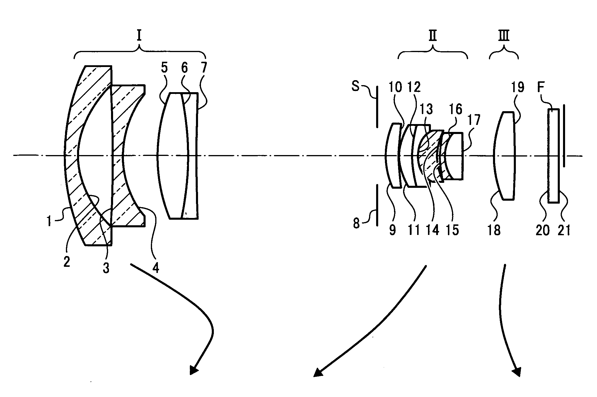
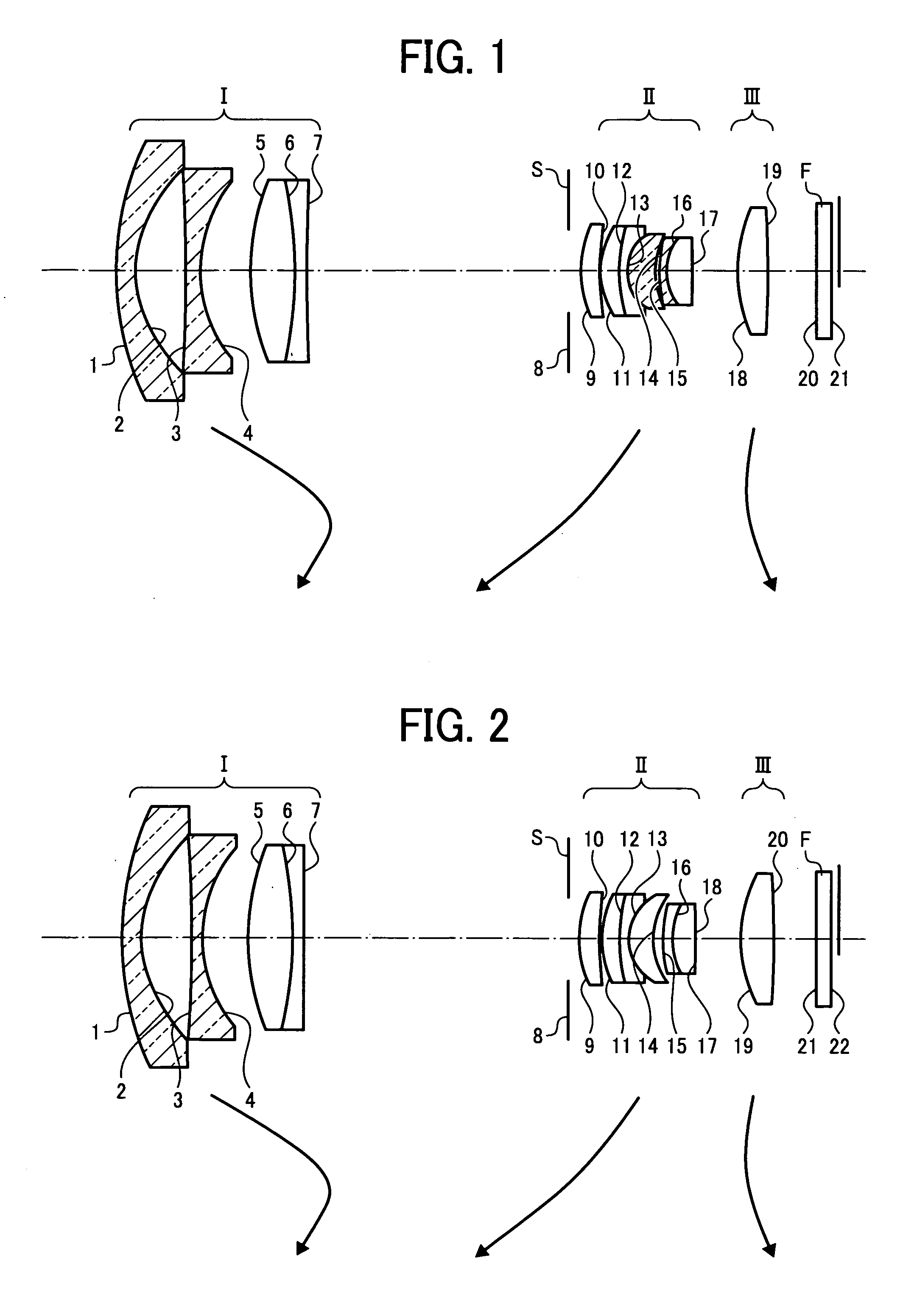
first embodiment
[0131]f=5.204˜14.996, F=2.66˜4.67, ω=43.26˜17.51
SurfaceNo.RDNdνdΔθg, Fname of glass type0124.4221.601.7331048.89−0.0093OHARA L-LAM72 02*9.2254.1103−180.1531.201.7725049.60−0.0092OHARA S-LAH660411.5844.100520.4983.551.8010034.970.0015OHARA S-LAM6606−34.3601.001.7570047.82−0.0076OHARA S-LAM5407232.236variable (A)08An aperture1.00 09*8.8211.561.7725049.60−0.0092OHARA S-LAH661022.8990.10117.0721.451.8044039.59−0.0045OHARA S-LAH631211.3550.701.8010034.970.0015OHARA S-LAM66133.8972.251.4874970.240.0022OHARA S-FSL5146.5720.331511.1420.601.7495035.280.0025OHARA S-LAM7164.2052.131.4970081.540.0280OHARA S-FPL51 17*−100.000variable (B)1812.9522.501.4387594.940.0461OHARA S-FPL53 19*−153.191variable (C)20∞1.241.5168064.20Various filters21∞
[0132](Aspheric Surfaces)
[0133]“*” symbols are given to aspheric surfaces. The following embodiments are the same as above.
[0134](Second Surface)[0135]K=0.0,[0136]A4=−1.28414×10⁻⁴, A6=−6.57446×10⁻⁷, A8=−6.30308×10⁻⁹,[0137]A10=−1.72874×10⁻¹⁰, A12=−2.57252×10⁻¹²,...
second embodiment
[0157]f=5.201˜14.992, F=2.61˜4.55, ω=43.30˜17.52
Surface No.RDNdνdΔθg, FName of glass type0124.7781.601.7331048.89−0.0093OHARA L-LAM72 02*9.2584.1303−135.5120.901.7725049.60−0.0092OHARA S-LAH660411.4503.680520.0523.621.8010034.970.0015OHARA S-LAM6606−31.6780.801.7570047.82−0.0076OHARA S-LAM5407575.312variable(A)08An aperture1.00 09*8.0591.701.7725049.60−0.0092OHARA S-LAH661033.1970.23118.3471.411.7432049.34−0.0085OHARA S-LAM601215.1240.741.8010034.970.0015OHARA S-LAM66134.0001.971.4874970.240.0022OHARA S-FSL5145.8360.811511.5910.761.6989530.130.0103OHARA S-TIM35166.0991.801.4387594.940.0461OHARA S-FPL5317−83.4370.041.5200052.00A resin layer 18*−92.525variable(B)1911.3932.771.4387594.940.0461OHARA S-FPL53 20*−173.335variable(C)21∞1.241.5168064.20Various filters22∞
[0158](Aspheric Surfaces)
[0159](Second Surface)[0160]K=0.0,[0161]A4=−1.35800×10⁻⁴, A6=−6.92172×10⁻⁷, A8=−6.14443×10⁻⁹,[0162]A10=−1.43503×10⁻¹⁰,[0163]A12=−3.48101×10⁻¹², A14=2.10140×10⁻¹⁴, A16=9.10457×10⁻¹⁶,[0164]A18=−1.22550×...
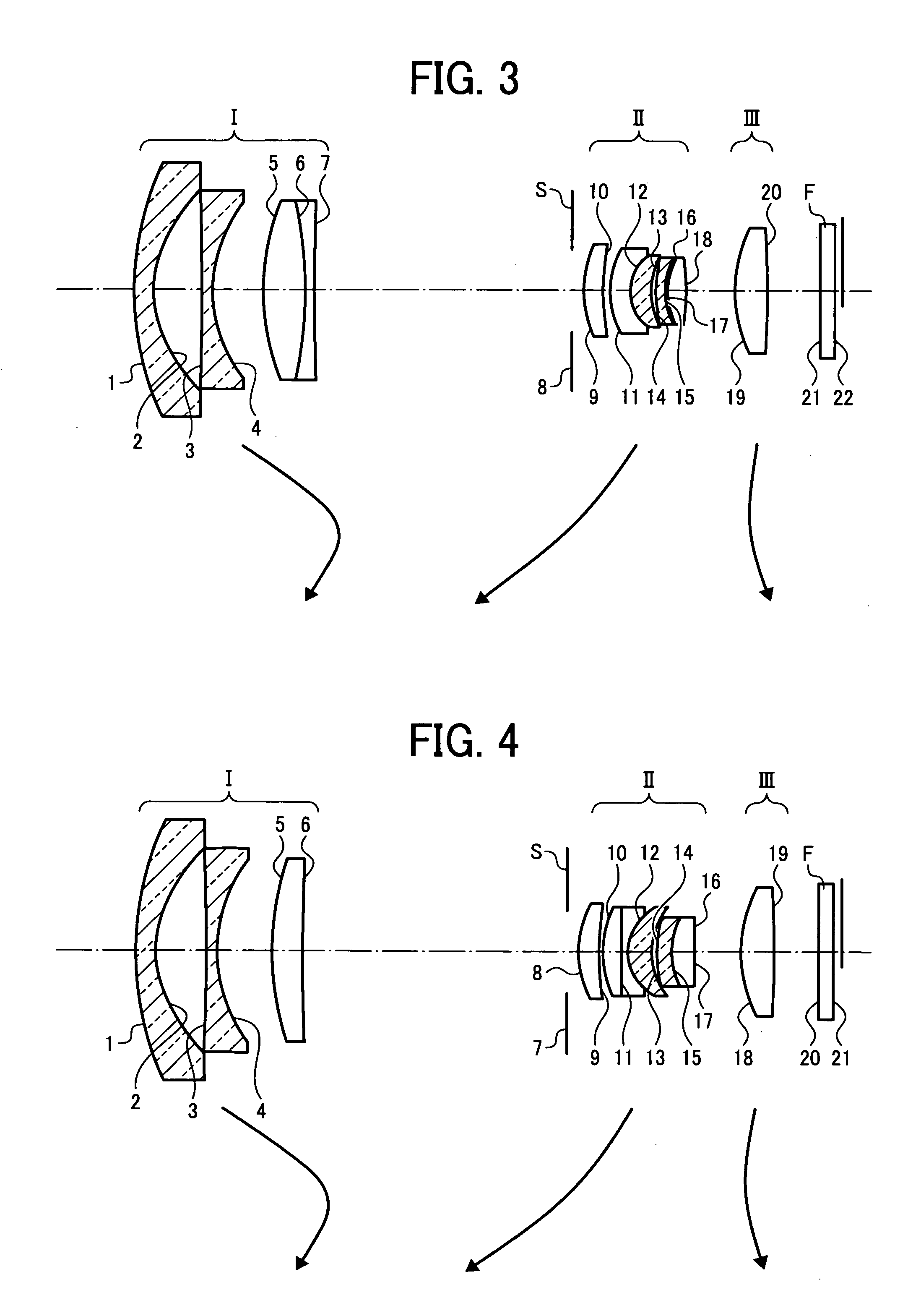
third embodiment
[0183]f=5.204˜15.004, F=2.64˜4.66, ω=43.27˜17.52
Surface No.RDNdνdΔθg, FName of glass type0125.3881.601.7331048.89−0.0093OHARA L-LAM72 02*9.1924.0303−284.8030.901.7725049.60−0.0092OHARA S-LAH660411.7994.270520.8683.431.8010034.970.0015OHARA S-LAM6606−34.9270.801.7570047.82−0.0076OHARA S-LAM5407206.277variable(A)08An aperture1.00 09*8.0321.651.7995242.22−0.0060OHARA S-LAH521022.9230.57117.3491.691.7847026.290.0146OHARA S-TIH23123.7901.741.4874970.240.0022OHARA S-FSL5136.4870.441415.1890.751.7495035.280.0025OHARA S-LAM7156.1680.16 16*6.9770.121.5200052.00A resin layer176.5891.501.4387594.940.0461OHARA S-FPL5318−22.660variable(B)1912.6592.721.4387594.940.0461OHARA S-FPL53 20*−112.732variable(C)21∞1.241.5168064.20Various filters22∞
[0184](Aspheric Surface)
[0185](Second Surface)[0186]K=0.0,[0187]A4=−1.36863×10⁻⁴, A6=−6.47708×10⁻⁷, A8=−7.35880×10⁻⁹,[0188]A10=−1.35479×10⁻¹⁰, A12=−3.38913×10⁻¹², A14=2.21060×10⁻¹⁴,[0189]A16=9.07422×10⁻⁶, A18=−1.29112×10⁻¹⁷
[0190](9th Surface)[0191]K=0.0,[0192]...
PUM
 Abstract
Description
Claims
Application Information