Heat sink fastening assembly

a technology for fastening and sinks, which is applied in the direction of snap fasteners, lighting and heating apparatus, and semiconductor/solid-state device details. it can solve the problems of large free space for users to operate the handles, prone to damage other electronic components, and awkward operation of the fastener

Inactive Publication Date: 2008-06-26
HON HAI PRECISION IND CO LTD +1
View PDF15 Cites 7 Cited by
  • Summary
  • Abstract
  • Description
  • Claims
  • Application Information

AI Technical Summary

Benefits of technology

[0007]What is needed thereof is a heat sink fastening assembly which has a low cost and can easily secure a heat sink to a heat-generating component whilst operation of the heat sink fastening assembly does not need large free space.

Problems solved by technology

However, it needs large free space for the user to operate the handle during assembling the heat sink to the heat-generating component.
Furthermore, the operation of the user to the handle is prone to damage other electronic components located around the heat-generating component.
This makes operation of the fastener awkward.
Finally, the fastener of the related art has a complicated structure, whereby it has a high cost.

Method used


Image

  • Heat sink fastening assembly
  • Heat sink fastening assembly
  • Heat sink fastening assembly

Examples


Embodiment Construction

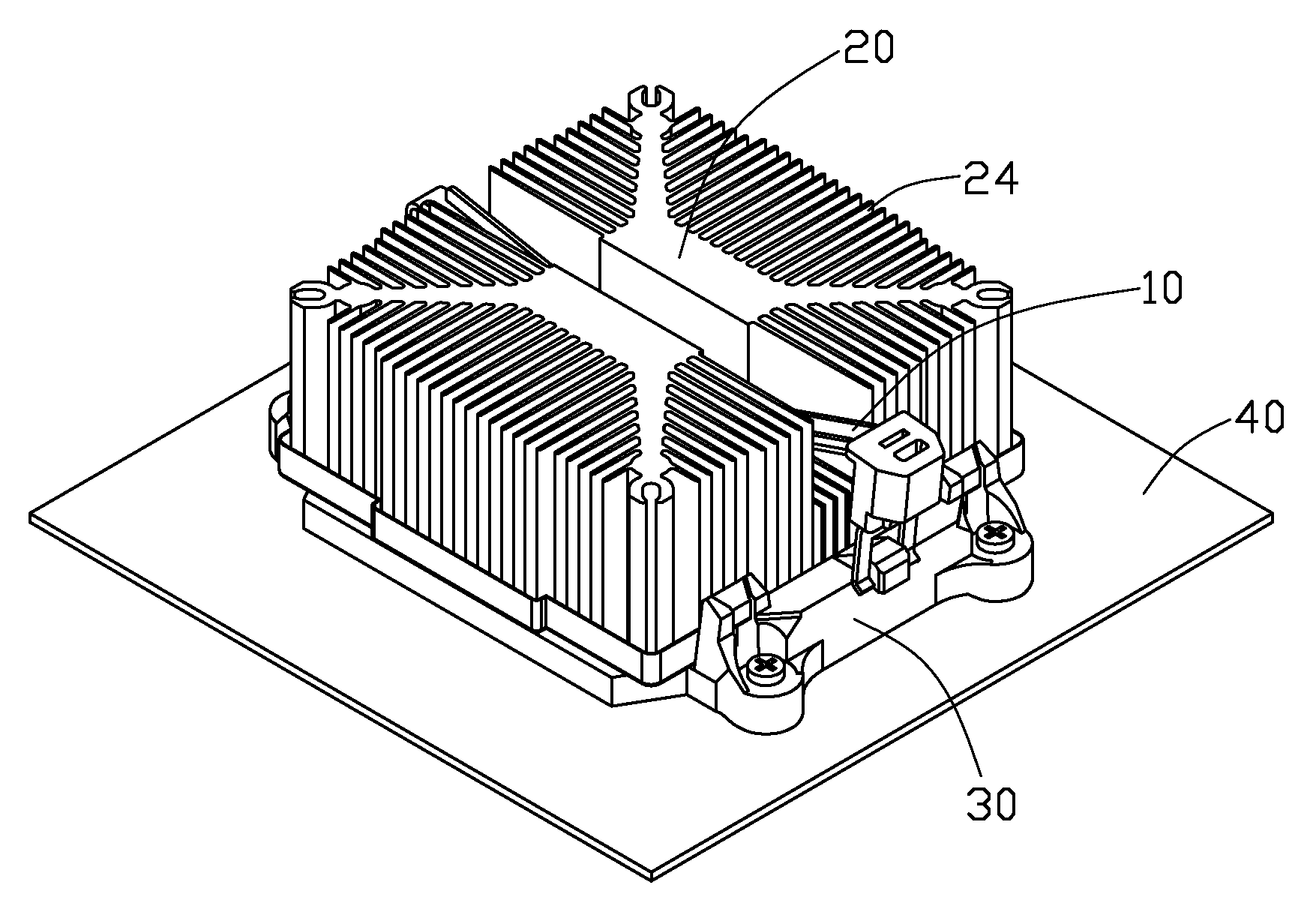
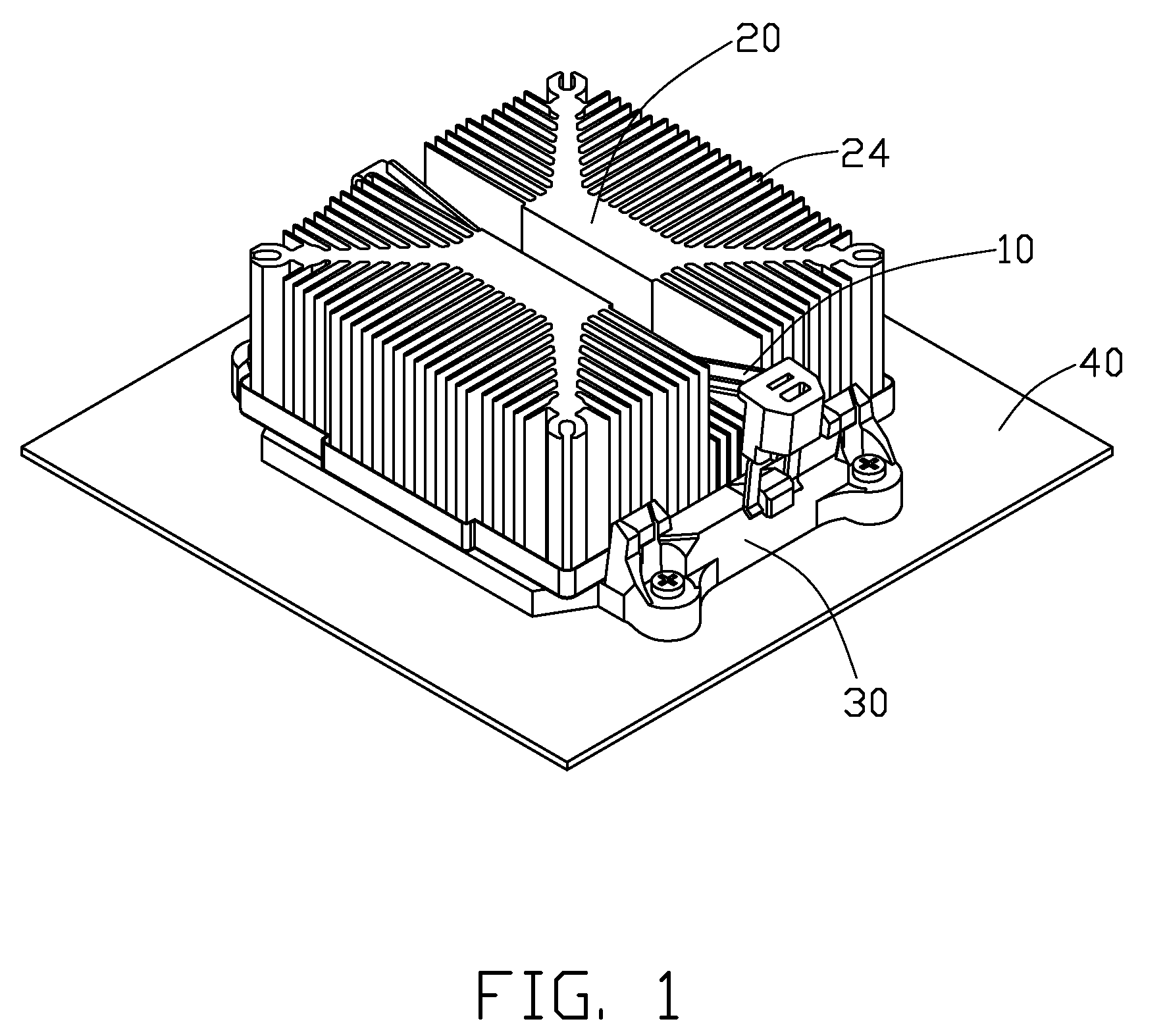
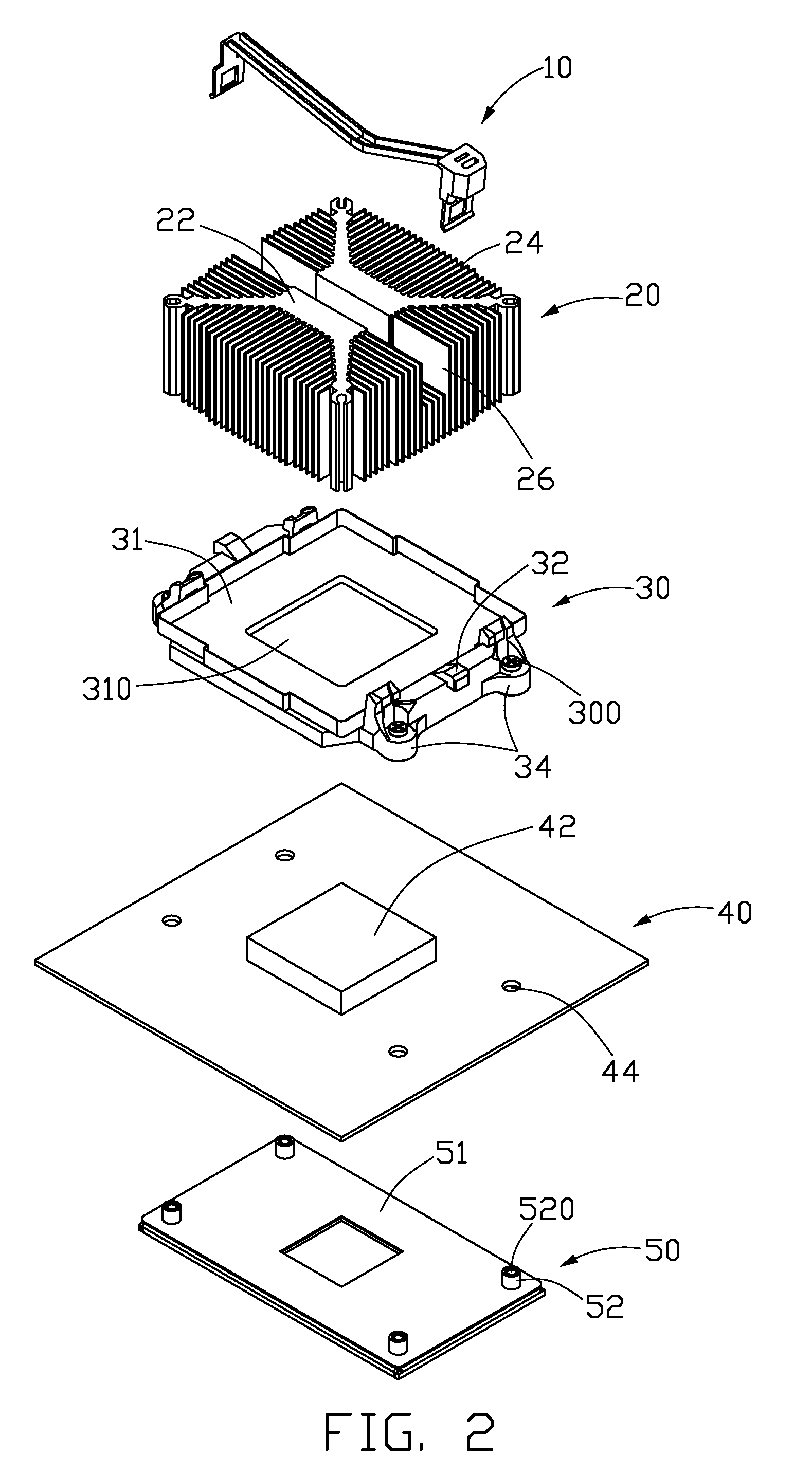
[0017]Referring to FIGS. 1 and 2, a heat sink fastening assembly in accordance with a preferred embodiment of the invention is used for attaching a heat sink 20 to a printed circuit board 40, for dissipating heat generated by a heat-generating component 42 mounted on the printed circuit board 40. The heat sink fastening assembly includes a fastener 10 for spanning over the heat sink 20 and a retention module 30 for engaging with the fastener 10 to clip the heat sink 20 therebetween. The retention module 30 is mounted on the printed circuit board 40 via a plurality of screws 300 extending through the printed circuit board 40 to engage with a back plate 50 located below the printed circuit board 40.

[0018]The back plate 50 comprises a substantially rectangular main body 51 and four posts 52 respectively extending upwardly from four corners of the main body 51. The posts 52 each define a mounting hole 520 for locking the screws 300.

[0019]The printed circuit board 40 defines four through...


PUM


Abstract

A heat sink fastening assembly includes a fastener comprising a latching member and an operating member. The latching member includes a pressing part, a first latching leg and a second latching leg bent downwards respectively from two opposite ends of the pressing part. The operating member has a coping and a sidewall extending downwards from an edge of the coping. The sidewall defines two locking slots engaging with the first latching leg and an elastic rib extending downwards from the coping and engaged with the first latching leg of the latching member for inhibiting any movement of the operating member in a direction along the locking slot of the sidewall.

Description

BACKGROUND OF THE INVENTION[0001]1. Field of the Invention[0002]The present invention relates to a heat sink fastening assembly, and particularly to a heat sink fastening assembly for securing a heat sink to a heat-generating component to remove heat from the heat-generating component.[0003]2. Description of Related Art[0004]Heat sinks are usually used to remove heat from heat-generating components, such as central processing units (CPUs) and the like, to keep the components at specified temperatures. A typical heat sink comprises a base, for contacting with the heat-generating component to absorb the heat generated by the heat-generating component, and a plurality of fins extending from the base for dissipating the heat into the ambient air.[0005]In order to secure the heat sink to the heat-generating component, a fastener is required. A fastener used for securing a heat sink to a heat-generating component is disclosed in US Patent Application Publication No. 2005 / 0144764 A1. The f...

Claims


Application Information

Patent Timeline
Patent Type & Authority Applications(United States)
IPC IPC(8): H05K7/20A44B99/00
CPCH01L23/4093H01L2924/0002Y10T24/44026H01L2924/00
Inventor WU, WEI-LELAI, CHENG-TIEN
Owner HON HAI PRECISION IND CO LTD
Why Eureka
Try Eureka