Light guide plate with light diffusing structure, backlight module and liquid crystal display using same

a technology of light diffusing structure and light guide plate, which is applied in the direction of planar/plate-like light guide, lighting and heating apparatus, instruments, etc., can solve the problem of visibly impaired performance of associated lcd

Inactive Publication Date: 2008-06-26
INNOCOM TECH SHENZHEN
View PDF7 Cites 7 Cited by
  • Summary
  • Abstract
  • Description
  • Claims
  • Application Information

AI Technical Summary

Benefits of technology

[0006]A light guide plate includes a main body and a protrusion. The main body includes a plurality of side surfaces. At least one of the side surfaces is a reflective side surface. The protrusion extends from one of the side surfaces. The protrusion includes a light incident side surface and a reflective side surface connected with the at least one reflective side surface of the main body. The main body defines a light emitting area. Incident light beams emitted from the light incident side surface of the protrusion are reflected by the reflective side surfaces of the main body and the protrusion once or more than once. Thereby, the reflective light beams have a divergence angle larger than a divergence angle of the incident light beams. The reflective light beams are transmitted to the light emitting area of the main body and are converted into flat light therein.

Problems solved by technology

As a result, the performance of an associated LCD may be visibly impaired.

Method used


Image

  • Light guide plate with light diffusing structure, backlight module and liquid crystal display using same
  • Light guide plate with light diffusing structure, backlight module and liquid crystal display using same
  • Light guide plate with light diffusing structure, backlight module and liquid crystal display using same

Examples


first embodiment

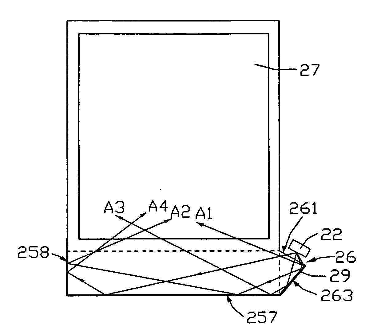
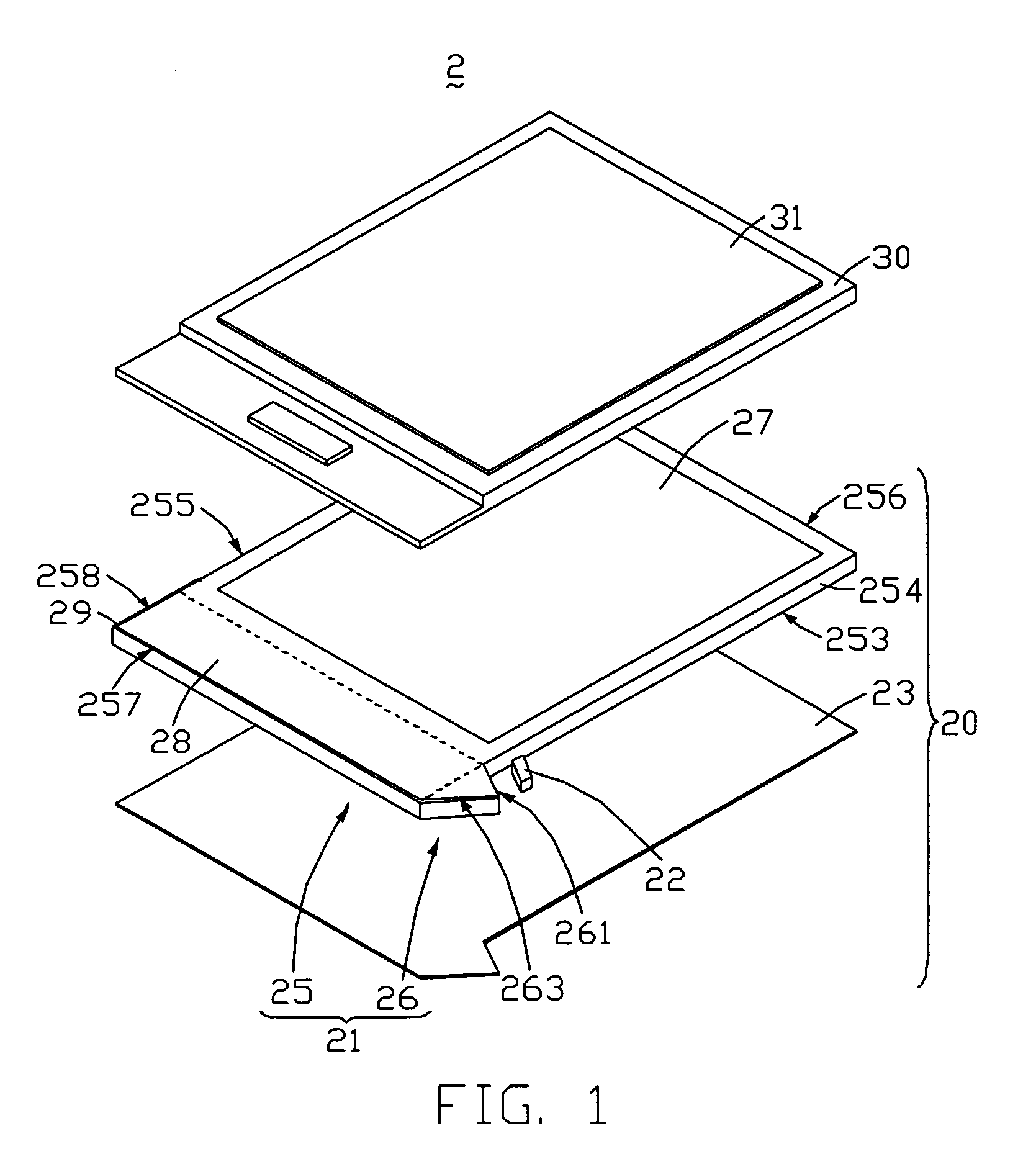
[0018]FIG. 1 is an isometric, exploded view of an LCD 2 according to the present invention. The LCD 2 includes a liquid crystal panel 30 and a backlight module 20 disposed under the liquid crystal display panel 30. The backlight module 20 provides flat and uniform light for illuminating the liquid crystal display panel 30. The liquid crystal panel 30 defines a display area 31 for displaying images and a non-display area (not labeled) for bonding drive circuits (not labeled).

[0019]The backlight module 20 includes an LGP 21, a light source 22, and a reflector 23. The reflector 23 is disposed under the LGP 21. In the illustrated embodiment, the light source 22 is an LED.

[0020]The LGP 21 includes a main body 25 and a protrusion 26 extending from the main body 25. The protrusion 26 has a thickness the same as the main body 25 and is substantially coplanar with the main body 25.

[0021]The main body 25 has a rectangular shape and includes a top surface (not labeled), a bottom surface 253, a...

second embodiment

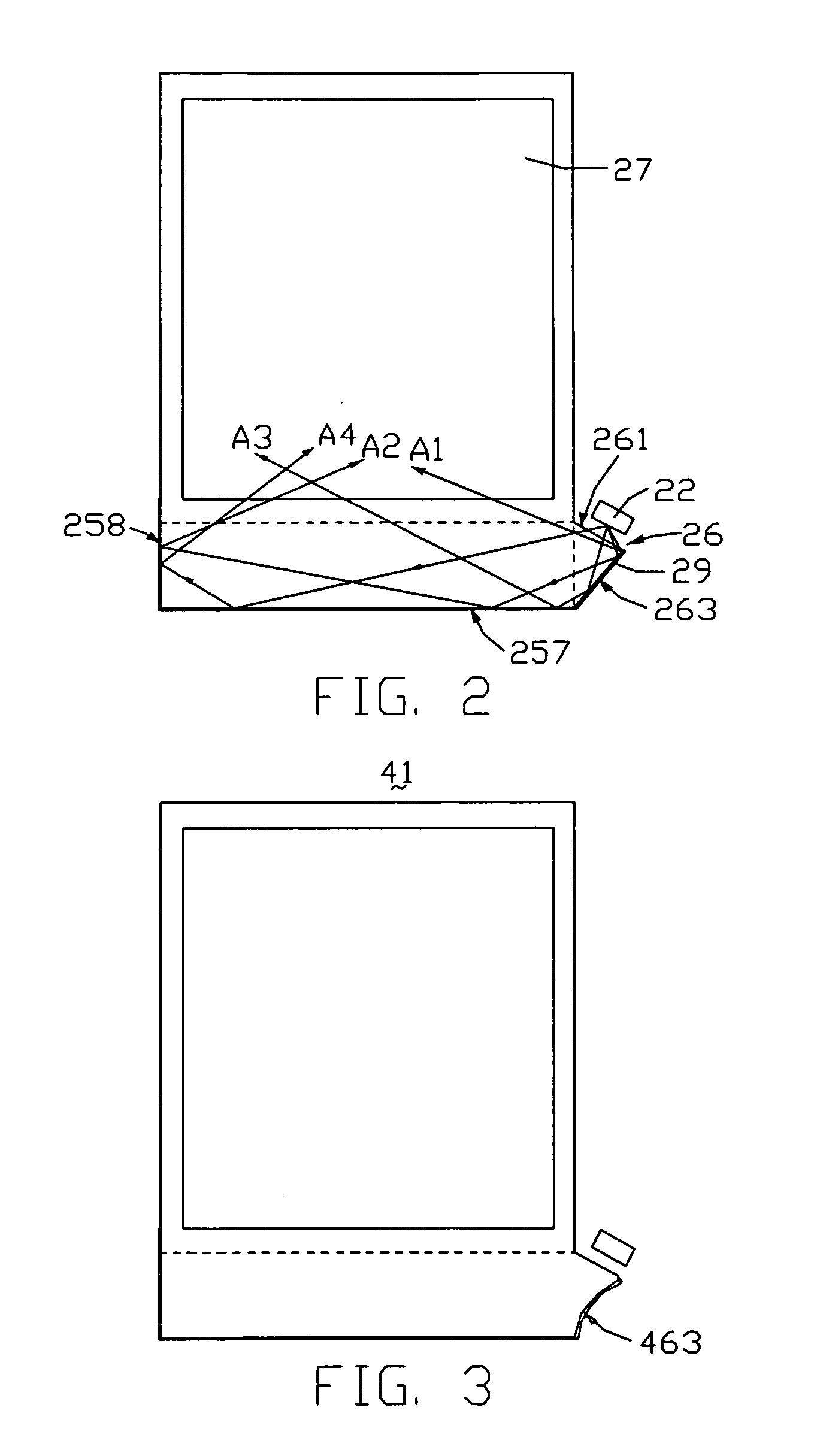
[0029]FIG. 3 is a top plan view of an LGP 41 of an LCD according to the present invention. The LGP 41 has a structure similar to that of the LGP 21. However, a sixth side surface 463 is a concave surface.

third embodiment

[0030]FIG. 4 is a top plan view of an LGP 51 of an LCD according to the present invention. The LGP 51 has a structure similar to that of the LGP 21. However, the LGP 51 includes a cut angle (not labeled) between a second side surface 555 and a fourth side surface 557. The cut angle defines a seventh side surface 568. The seventh side surface 568 and the second side surface 555 maintain a fourth crossing angle varied in the range from 120 degrees to 150 degrees. The seventh side surface 568 and the fourth side surface 557 maintain a fifth crossing angle varied in the range from 120 degrees to 150 degrees. A reflector layer 59 covers the seventh side surface 568, the fourth side surface 557, a sixth side surface (not labeled), and a reflective area 558 of the second side surface 555.

[0031]The LGP 51 includes the seventh side surfaces 568 located in a direction different from the second and fourth side surfaces 555, 557. Therefore, incident light beams may be further reflected by the s...


PUM


Abstract

An exemplary light guide plate (21) includes a main body (25) and a protrusion (26). The main body includes a plurality of side surfaces. At least one of the side surfaces is a reflective side surface. The protrusion extends from one of the side surfaces. The protrusion includes a light incident side surface (261) and a reflective side surface (263). The main body defines a light emitting area (27). Incident light beams emitted from the light incident side surface of the protrusion are reflected by the reflective side surfaces of the main body and the protrusion once or more than once. Thereby, the reflective light beams have a divergence angle larger than a divergence angle of the incident light beams. The reflective light beams are transmitted to the light emitting area of the main body and are converted into flat light therein.

Description

FIELD OF THE INVENTION[0001]The present invention relates to a light guide plate with light diffusing structure. The present invention also relates to a backlight module and a liquid crystal display using the light guide plate.GENERAL BACKGROUND[0002]Liquid crystal of a liquid crystal display (LCD) does no itself emit light. Therefore it is common for a backlight module to be installed in an LCD together with the LCD. The backlight module provides uniform flat light to enable the LCD to display images.[0003]FIG. 7 is a top plan view of certain components of a conventional backlight module. The backlight module 1 includes a light guide plate (LGP) 13 and four light emitting diodes (LEDs) 12. The LGP 13 includes a side surface 131 for receiving incident light, and a top surface 133 for emitting flat light. The top surface 133 is generally perpendicularly connected with the side surface 131. The LEDs 12 are disposed adjacent to the side surface 131 of the LGP 13.[0004]In operation, lig...

Claims


Application Information

Patent Timeline
Patent Type & Authority Applications(United States)
IPC IPC(8): F21V7/04
CPCG02B6/0031G02B6/0018
Inventor MA, XIAO-PING
Owner INNOCOM TECH SHENZHEN
Why Eureka
Try Eureka