Container for accommodating optical fiber coil and optical fiber module having the container

a technology for optical fiber modules and containers, applied in the field of containers for accommodating optical fiber coils and optical fiber modules having containers, can solve the problems of large connection loss, difficult exchange, and increase the number of connection points using optical connectors, and achieve the effect of simple configuration, reduced coil diameter of functional optical fibers, and convenient storag

Inactive Publication Date: 2008-06-26
SUMITOMO ELECTRIC IND LTD
View PDF25 Cites 61 Cited by
  • Summary
  • Abstract
  • Description
  • Claims
  • Application Information

AI Technical Summary

Benefits of technology

[0012]According to the present invention, the excess length portion of the pigtail optical fiber can be readily accommodated using a simple configuration, and without using a special accommodating mechanism. The optical fiber can be drawn outward to a desired length without being excessively bent, and connected to the external optical device at an appropriate length. Furthermore, the coil diameter of the functional optical fiber can be reduced, and the configuration of the optical fiber module can be made small and compact.

Problems solved by technology

This increases the number of connection points using optical connectors, and leads to a problem having large connection loss.
In addition, when optical damage leads to malfunctioning of the optical connection terminals, it is difficult to exchange it.
In addition, when optical damage causes a malfunction to occur in the optical connection terminals, it is easy to exchange it.
However, the mechanism accommodating the excess length portion is complex.
Furthermore, the bend radius tends to be relatively small, and a risk is presented that the pigtail optical fiber will be damaged.
Another problem with this configuration is that the excess length portion, which can be drawn out from the container, cannot be made very long.

Method used


Image

  • Container for accommodating optical fiber coil and optical fiber module having the container
  • Container for accommodating optical fiber coil and optical fiber module having the container
  • Container for accommodating optical fiber coil and optical fiber module having the container

Examples


Embodiment Construction

[0020]The above-mentioned features and other features, aspects, and advantages of the present invention will be better understood through the following description, appended claims, and accompanying drawings. In the explanation of the drawings, an identical mark is applied to identical elements and an overlapping explanation will be omitted.

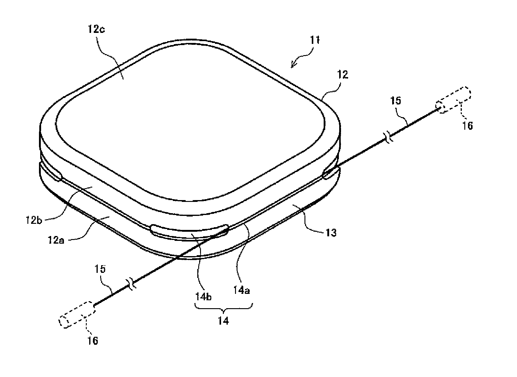
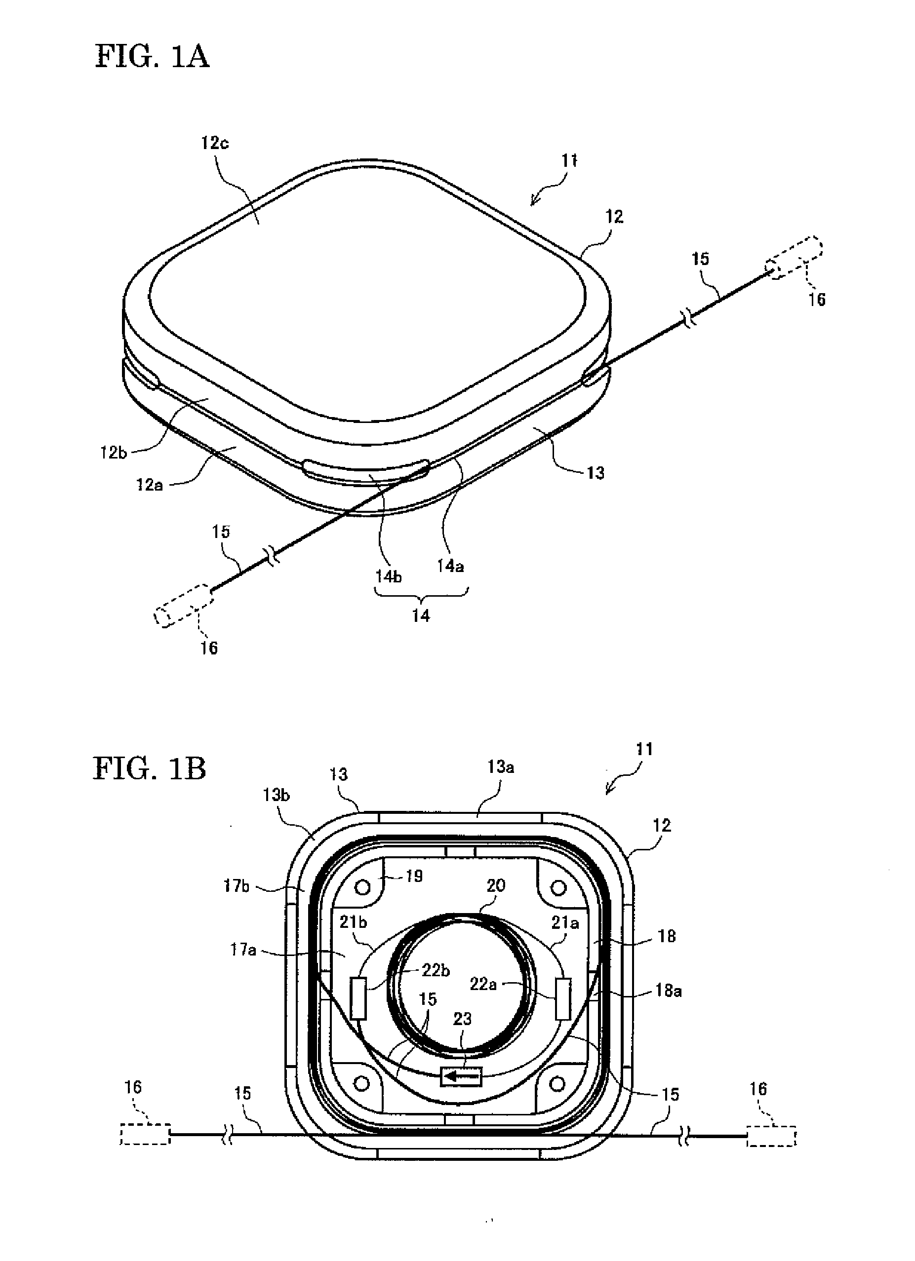
[0021]FIGS. 1A and 1B show an embodiment of an optical fiber module according to the present invention, with FIG. 1A being a perspective view, and FIG. 1B being a front view that shows a state wherein half of the container has been removed. A container 12 of an optical fiber module 11 is, for example, in a flat square shape, and the corner portions of the container 12 have a smooth, rounded shape. A sidewall 13 of the container 12 has a gap 14 that extends around the entire periphery of the sidewall 13. A label 12c or the like imprinted with specifications, manufacturing-related numbers, and other information relating to the optical fiber module ...


PUM


Abstract

A container for an optical fiber coil and an optical fiber module including the container is provided, wherein an excess length portion of a pigtail fiber is accommodated in the container and the remaining portion can be drawn out from the container. The container includes a first part for accommodating a coil having a functional optical fiber, and a second part disposed on an outer periphery side of the first part and windingly accommodating a pigtail fiber that is optically connected to the functional optical fiber. The second part has a gap that extends over the entirety of the outer periphery, and communicates with the exterior. The optical fiber module includes the container, the coil having the functional optical fiber accommodated in the first part of the container, and the pigtail fiber that is optically connected to the functional fiber and that has a portion windingly accommodated in the second part.

Description

BACKGROUND OF THE INVENTION[0001]1. Field of the Invention[0002]The present invention relates to a container for accommodating a coil comprising a functional optical fiber, and to an optical fiber module having the container.[0003]2. Description of the Background Arts[0004]Optical fiber modules comprise, for example, a box-shaped container, a functional optical fiber wound in a coil shape and accommodated in a container, and an optical connection terminal for establishing a connection to an external optical device provided to an end of the functional fiber. The functional optical fiber may be a dispersion compensating fiber (DCF), an optical amplifying fiber, a highly nonlinear fiber (HNLF), or the like. The optical fiber coil comprising the functional fiber is commonly accommodated in a container in a configuration wherein the optical fiber coil is wound around a bobbin, or is covered in a resin. The optical connection terminal is connected to input / output ends of the optical fiber...

Claims


Application Information

Patent Timeline
Patent Type & Authority Applications(United States)
IPC IPC(8): G02B6/00
CPCG02B6/4457
Inventor HIRANO, MASAAKIYAMAGUCHI, MASAHIROTSURUGA, MASAKI
Owner SUMITOMO ELECTRIC IND LTD
Why Eureka
Try Eureka