
Surgical instrument and osteosynthesis device

Active Publication Date: 2008-06-26
AESCULAP AG
View PDF13 Cites 71 Cited by
  • Summary
  • Abstract
  • Description
  • Claims
  • Application Information

AI Technical Summary

Benefits of technology

[0006]The surgical instrument according to the invention makes it possible to grasp the connection member when the instrument is in the release position and to lock or secure the instrument to the connection member by transferring the instrument from the release position to the connection position. In particular, a surgical instrument in accordance with the present invention offers the possibility that a person holding the instrument can release it without running the risk of losing the connection member inside or outside a human or animal body. The locking mechanism ensures that the connection member is securely held on the instrument when it assumes the connection position.
[0059]Preferably, the at least two bone anchorage elements comprise at least one bone screw having a U-shaped receptacle for receiving at least a part of the at least one connection member, the at least one bone screw comprising a fixing element for securing the at least one connection member in the receptacle in a connection position. A connection member, in particular, a connection member in the form of a rod, can be easily inserted into a U-shaped receptacle. Furthermore, such a rod or a rod portion of a connection plate can be fixed to the anchorage element in a desired relation by means of the fixing element. The fixing element can, for example, be designed in the form of a fixing screw.

Problems solved by technology

However, it is difficult to insert a connection member, for example, a connection rod into a corresponding retainer of the bone anchorage element, in particular, if only a minimal invasive access is used for inserting and fixing the device to the spinal column in a desired manner.
However, it is not easy to apply a connection rod with such instruments since they are not specifically adapted for such purposes.

Method used


Image

  • Surgical instrument and osteosynthesis device
  • Surgical instrument and osteosynthesis device
  • Surgical instrument and osteosynthesis device

Examples


Embodiment Construction

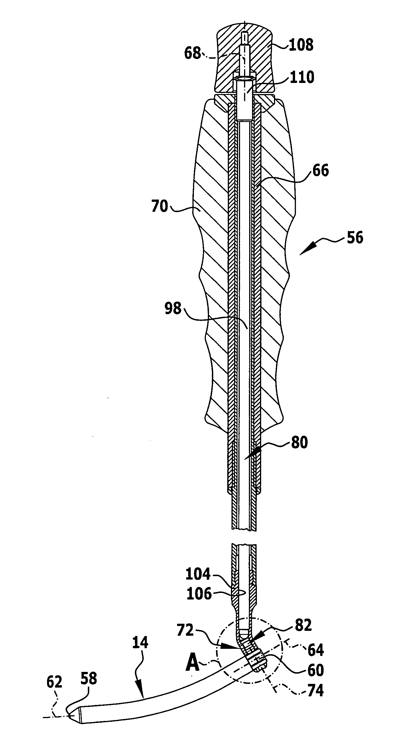
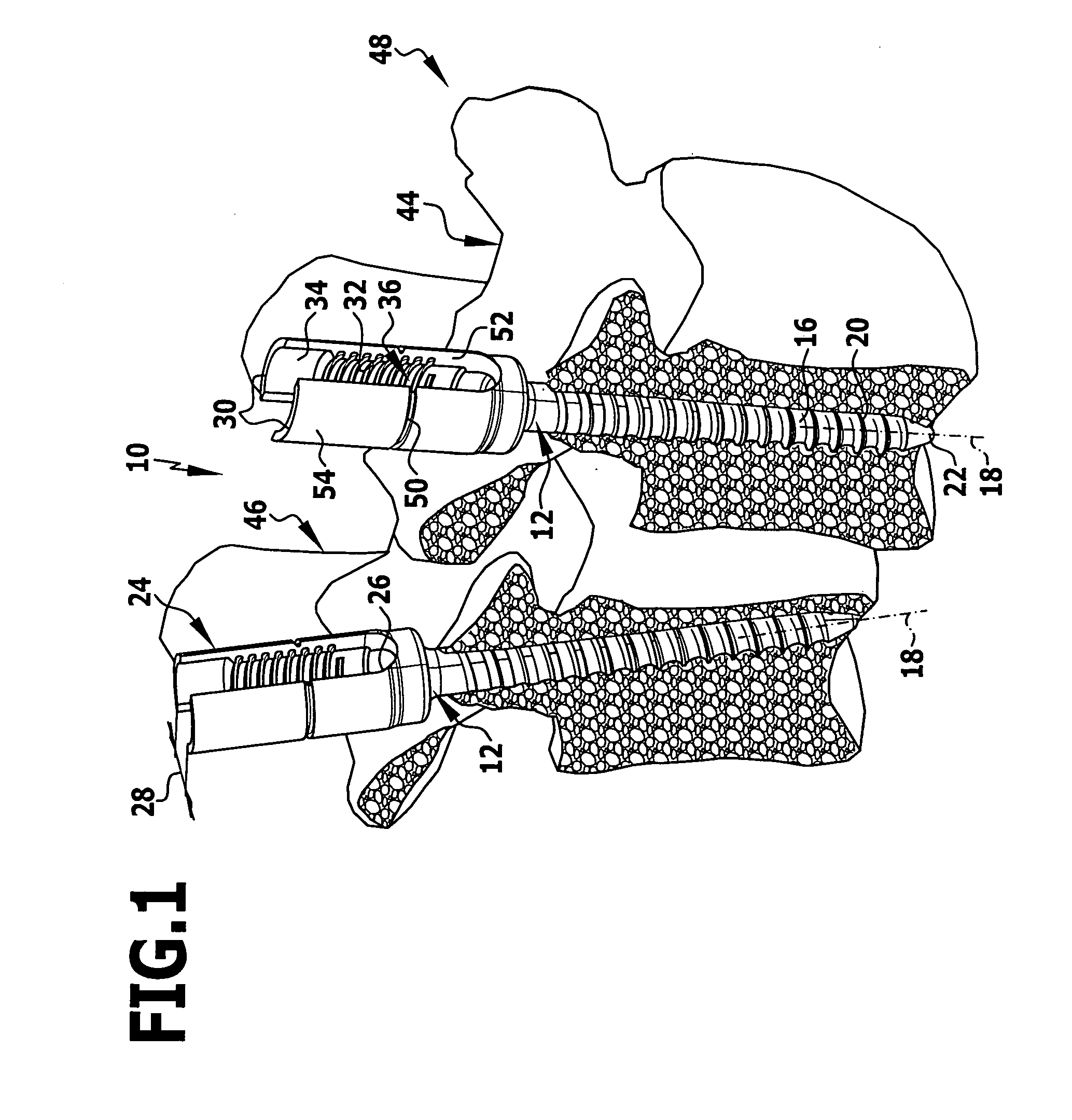
[0076]An osteosynthesis device 10 shown in the figures comprises at least two bone anchorage elements in the form of pedicle screws 12 and at least one connection member in the form of a curved rod 14 having a substantially circular cross section.

[0077]Each pedicle screw 12 comprises an elongated threaded shaft 16 defining a longitudinal axis 18. Threads 20 provided on the shaft 16 can be provided in the form of self-cutting threads. A distal end of the shaft 16 forms a screw tip 22. A proximal end of the pedicle screw 12 forms a bone anchorage element head in the form of U-shaped head or a fork head 24. The fork head 24 is substantially sleeve-shaped and comprises a slot 26 which serves as a connection member seating and can also be called a retainer or a connection member receptacle in which a connection member, for example, a rod 14 or a plate-like element having at least one rod-shaped section, can be seated. The slot 26 has the shape of a semicircle at its closed proximal end w...


PUM


Abstract

A surgical instrument for holding and inserting a connection member of an osteosynthesis device into a retainer of a bone anchorage element comprises a distal end, a proximal end and a first connection portion at a distal end. The first connection portion comprises a connection member receptacle for receiving at least a portion of the connection member. The instrument further comprises a locking mechanism which is transferable from a release position, in which the instrument is releasable from the connection member, to a connection position, in which the instrument can be connected to the connection member. Moreover, an osteosynthesis device comprising at least two bone anchorage elements and at least a connection member is proposed, which further comprises a surgical instrument for holding and inserting the connection member into at least one retainer of the bone anchorage elements.

Description

FIELD OF THE INVENTION[0001]The present invention relates to a surgical instrument for holding and inserting a connection member of an osteosynthesis device into a retainer of a bone anchorage element, the instrument comprising a distal end, a proximal end and a first connection portion at the distal end.[0002]Furthermore, the present invention relates to an osteosynthesis device comprising at least two bone anchorage elements and at least one connection member, further comprising a surgical instrument for holding and inserting the connection member into a least one retainer of the bone anchorage elements, the instrument comprising a distal end, a proximal end and a first connection portion at the distal end.BACKGROUND OF THE INVENTION[0003]Osteosynthesis devices of the type described hereinabove are used, for example, to fasten two vertebrae of a human spinal column relative to each other, either because a vertebra is, damaged or because a disc connecting the two vertebrae is damag...

Claims


Application Information

Patent Timeline
IPC IPC(8): A61B17/58
CPCA61B17/701A61B17/7011A61B2019/307A61B17/7083A61B17/708A61B17/7032A61B2090/037
Inventor SCHUMACHER, JOERGDALTON, BRIAN E.HAHN, ULRICH
Owner AESCULAP AG
Features
  • Generate Ideas
  • Intellectual Property
  • Life Sciences
  • Materials
  • Tech Scout
  • Unparalleled Data Quality
  • Higher Quality Content
  • 60% Fewer Hallucinations
Learn More