
Broadcasting receiver and communication method using the broadcasting receiver

Active Publication Date: 2008-06-26
LG ELECTRONICS INC
View PDF17 Cites 1 Cited by
  • Summary
  • Abstract
  • Description
  • Claims
  • Application Information

AI Technical Summary

Benefits of technology

[0012]Another object of the present invention is to provide a broadcasting receiver capable of efficiently operating an IP process according to a mode of a cable card and a method of controlling the IP process.
[0016]It is possible to acquire the IP addresses for the host and the cable card via one physical interface. In addition, it is possible to stabilize an overall system by efficiently operating the IP process according to an operation mode of the cable card.

Problems solved by technology

However, the cable card only performs communication based on a host-cable card interface (CCIP) standard and does not include an interface which can perform IP network communication.
Accordingly, it is impossible for the cable card to independently receive the IP address and perform the IP network communication.

Method used


Image

  • Broadcasting receiver and communication method using the broadcasting receiver
  • Broadcasting receiver and communication method using the broadcasting receiver
  • Broadcasting receiver and communication method using the broadcasting receiver

Examples


Embodiment Construction

[0028]Reference will now be made in detail to the preferred embodiments of the present invention, examples of which are illustrated in the accompanying draings. Wherever possible, the same reference numbers will be used throughout the drawings to refer to the same or like parts.

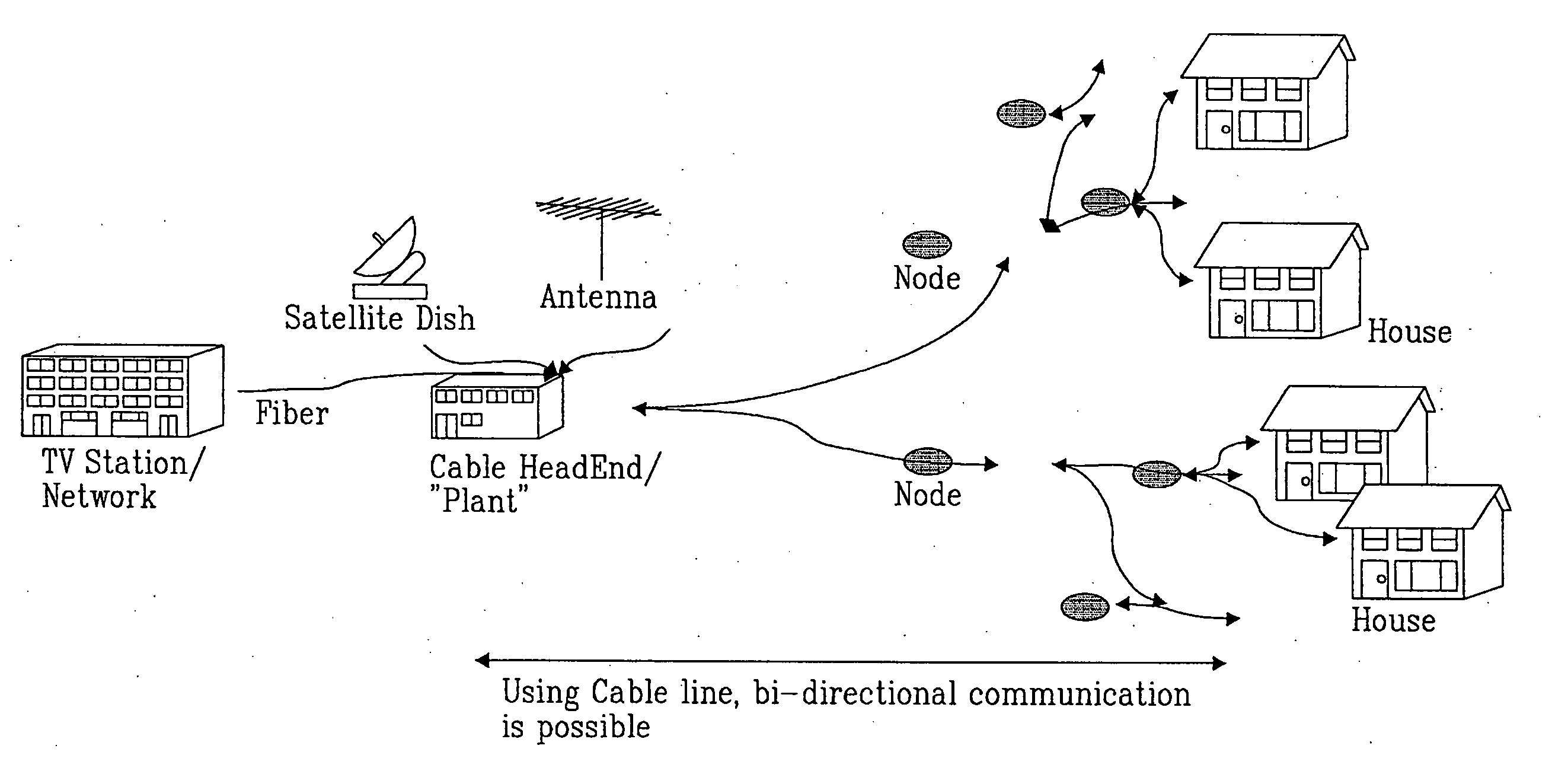
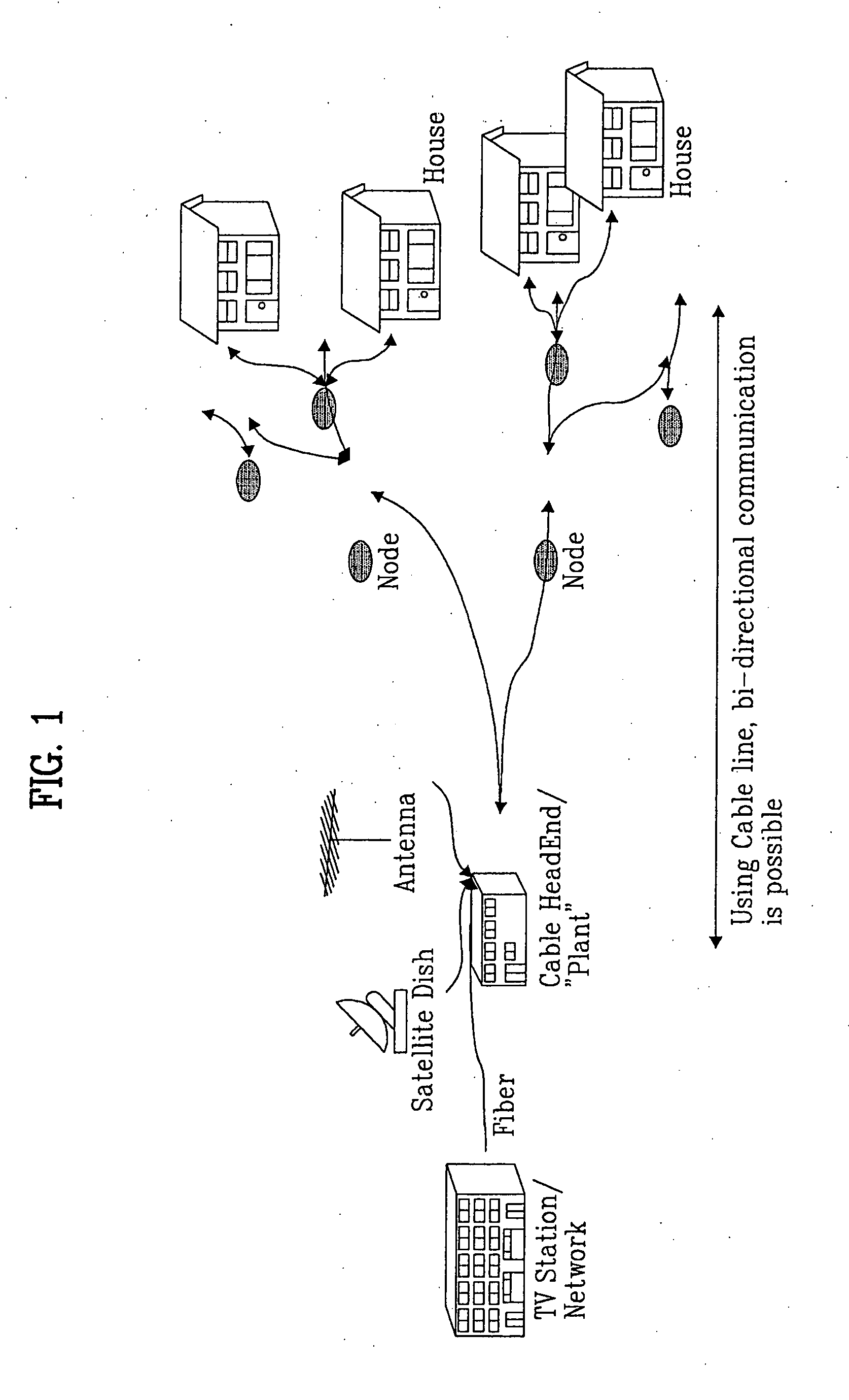
[0029]FIG. 1 is a conceptual diagram of a broadcasting network in digital cable broadcasting. Referring to FIG. 1, a cable headend (hereinafter, referred to as a headend) or a plant can receive a broadcasting signal via various communication networks.

[0030]The headend can transmit the cable broadcasting signal, which is received via the various communication networks, to a cable broadcasting receiver via a network including a node. The cable broadcasting receiver can receive the broadcasting signal from the headend or transmit a specific signal to the headend. At this time, the transmission / reception is realized via a cable network shown in FIG. 1, which can bi-directionally transmit data.

[0031]A host can be ...


PUM


Abstract

A method of performing communication between an Internet protocol (IP) address allocation server and an apparatus including a cable card and a host device is disclosed. In the communication method, the host acquires identification information of the cable card and transmits a message including the identification information of the cable card to the IP address allocation server. The host receives an IP address for the cable card from the IP address allocation server and sends the received IP address for the cable card to the cable card. Accordingly, it is possible to acquire the IP addresses for the host and the cable card via one physical interface. In addition, it is possible to stabilize an overall system by efficiently operating the IP process according to an operation mode of the cable card.

Description

[0001]This application claims the benefit of Korean Patent Application No. 10-2006-0130997, filed on Dec. 20, 2006, which is hereby incorporated by reference as if fully set forth herein.BACKGROUND OF THE INVENTION[0002]1. Field of the Invention[0003]The present invention relates to a broadcasting receiver and a communication method using the broadcasting receiver.[0004]2. Discussion of the Related Art[0005]In an existing one-way cable television (TV) system, since necessary data is received through a down channel, an Internet protocol (IP) address is not required. In contrast, in a two-way cable TV system, since network communication using a down channel and an up channel is possible, an IP address for IP communication needs to be acquired. The cable TV system can perform communication according to RFC 2131 and RFC 2132 using a dynamic host configuration protocol (DHCP), for two-way IP communication.[0006]In general, an IP address is allocated to a physical interface in one-to-one ...

Claims


Application Information

Patent Timeline
IPC IPC(8): H04N7/00H04N7/173
CPCH04L29/1282H04L61/2015H04N21/6402H04N7/17318H04L61/6013H04L61/59H04L61/5014H04N21/60
Inventor CHUN, WON HO
Owner LG ELECTRONICS INC
Learn More