Power and Communication Distribution Using a Structural Channel Stystem

a technology of structural channel system and distribution channel, which is applied in the direction of girders, filing appliances, machine supports, etc., can solve the problems of inflexibility, difficult, costly and time-consuming to change the structure of the commercial interior, and the complexity of planning and managing the commercial interior

Inactive Publication Date: 2008-07-03
HOWE RUSSEL +3
View PDF10 Cites 79 Cited by
  • Summary
  • Abstract
  • Description
  • Claims
  • Application Information

AI Technical Summary

Benefits of technology

[0066]The application devices can include at least one controlling device, with the device having signal generating means for generating a first of communication signals. The application devices can also include at least one controlled device, with the controlled device being associated with one of the series of connector modules, and having at least first and second states. The first set of communication signals is utilized to effect a logical control relationship between the controlling device and the controlled device, so that the controlling device controls whether the controlled device is in the first state or the second state. The logical control relationship between the controlling device and the controlled device is capable of reconfiguration, at least in part, with a second set of communication signals, in the absence of any physical relocation or physical rewiring associated with the controlling device and the controlled device. The controlling device can be communicatively coupled to a first one of the connector modules, and the first set of communication signals applied to the communications distribution means through the first connector module. The controlled device can be electrically coupled to a second one of the connector modules, with the second one of the connector modules being responsive to the first set of communication signals to selectively apply electrical power to the controlled device, so as to cause the controlled device to function in either the first state or the second state.
[0067]The controlling device can include processor means responsive to external control signals for generating communication signals so as to effect the logical control relationship between the controlling device and the controlled device. The controlling device can be electrically coupled to a first connector module through one or more connector ports and at least one patch cord. The patch cord and the connector ports can be adapted to apply DC power from the first connector module to the controlling device.

Problems solved by technology

Given the use of stationary walls and heavy equipment, any reconfiguration of a commercial interior was a time-consuming and costly undertaking.
These factors have added considerably to the complexity of planning and managing commercial interiors.
The confluence of these conditions has resulted in commercial interiors being inflexible and difficult and costly to change.
However, when these structures, which can be characterized as somewhat “permanent” in most buildings, are designed, the actual occupants may not move into the building for several months or even years.
Needless to say, in situations where the building will not be commissioned for a substantial period of time after the design phase, the infrastructure of the building may not be appropriately laid out for the actual occupants.
However, most commercial interiors permit little reconfiguration after completion of the initial design.
Reconfiguring a structure for the needs of a particular tenant can be extremely expensive and time consuming.
However, many organizations today experience relatively rapid changes in growth, both positively and negatively.
When these changes occur, again it may be difficult to appropriately modify the commercial interior so as to permit the occupant to expand beyond its original commercial interior or, alternatively, be reduced in size such that unused space can then be occupied by another tenant.
Other problems also exist with respect to the layout and organization of today's commercial interiors.
To modify these control relationships in most commercial interiors requires significant efforts.
Current systems do not provide for any relatively easy “reconfiguration,” either with respect to electrical or “logical” relationships (e.g. the control of a particular bank of lights by a particular set of switches), or mechanical structure.
This often results in difficulty with respect to providing power and communications distribution throughout locations within a commercial interior.
It may therefore be difficult to establish a “mechanically efficient” system for carrying electrical power, and yet still meet appropriate codes and regulations.
Regulations and standards directed to these and similar issues have made it substantially difficult to develop efficient power and communications distribution systems.
Other difficulties also exist.
With respect to other issues associated with providing a distributed power structure, the carrying of high voltage lines are subject to a number of relatively restrictive codes and regulations.
Still further, to provide for a distributed power and communication system for reconfigurable applications, physically realizable limitations exist with respect to system size.
For example, and particularly with respect to DC communication signals, limitations exist on the transmission length of such signals, regarding attenuation, S / N ratio, etc.
Such limitations may correspondingly limit the physical size of the structure carrying power and communications signals.
Other difficulties may also arise with respect to overhead systems for distributing power.
However, extremely strict building codes exist with respect to any type of overhead structures carrying AC electrical power, particularly high voltage power.
An inverted T-runner is engaged with the spline, in a manner so that when the ceiling system is exposed to heat, the inverted T-runner continues to hold the ceiling panels even, although the spline loses structural integrity and may disengage from the trim.

Method used


Image

  • Power and Communication Distribution Using a Structural Channel Stystem
  • Power and Communication Distribution Using a Structural Channel Stystem
  • Power and Communication Distribution Using a Structural Channel Stystem

Examples


Embodiment Construction

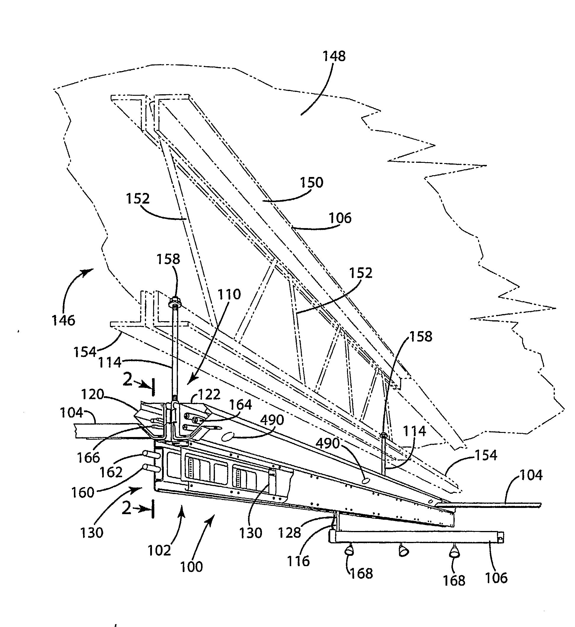
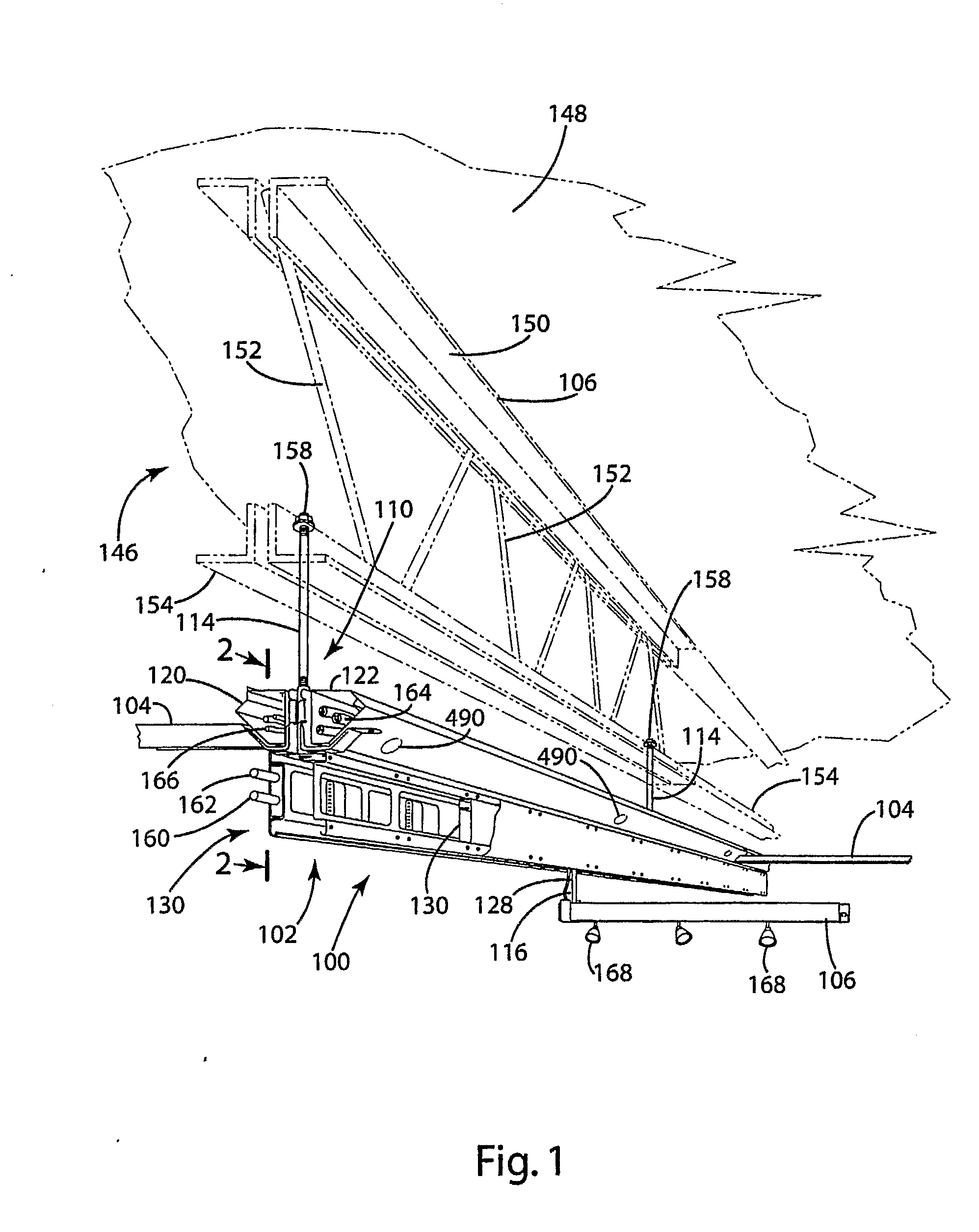
[0186]The principles of the invention are disclosed, by way of example, within a structural channel system 100 illustrated in FIGS. 1-92. A perspective view of major components of the structural channel system 100, as installed within a building structure which may comprise a reconfigurable commercial interior, is illustrated in FIG. 1. A structural layout of the structural channel system 100 employing certain of its components is illustrated in FIG. 4. The structural channel system 100 comprises an overhead structure providing significant advantages in environmental workspaces. As examples, the structural channel system 100 in accordance with the invention facilitates access to locations where a commercial interior designer may wish to locate various functional elements, including lighting, sound equipment, projection equipment (both screens and projectors), power poles, other means for energizing and providing data to and from electrical and communication devices, and other utilit...


PUM


Abstract

A structural channel system (100) includes a main structural channel rail (102), cross-channels (104) and cross-rails (106). A modular plug assembly (130) couples electrical power and communication signals to connector modules (132, 140, 144) which, in turn, control application of power to application devices (939, 969) based on the communication signals.

Description

CROSS-REFERENCE TO RELATED APPLICATIONS[0001]Not applicable.STATEMENT REGARDING FEDERALLY SPONSORED RESEARCH OR DEVELOPMENT[0002]Not applicable.REFERENCE TO A MICROFISHE APPENDIX[0003]Not applicable.BACKGROUND OF THE INVENTION[0004]1. Field of the Invention[0005]The invention relates to overhead structures for commercial interiors (i.e., commercial, industrial and office environments) requiring power for energizing lighting, audio-visual, acoustical management, security and other applications and, more particularly, to a distributed power and communications network using a structural channel system which permits electrical and mechanical interconnections (and reconfiguration of electrical and mechanical interconnections) of various applications, and communications (including programmed reconfiguration of controlled / controlling relationships) among application devices.[0006]2. Background Art[0007]Building infrastructure continue to evolve in today's commercial, industrial and office ...

Claims


Application Information

Patent Timeline
Patent Type & Authority Applications(United States)
IPC IPC(8): E04C3/08A47F5/01F16M13/02E04C3/04E04B9/18H02G3/36
CPCH02G3/00
Inventor HOWE, RUSSELHILLIS, DANIEL W.INSALACO, ROBERT W.LONG, JAMES B.
Owner HOWE RUSSEL
Why Eureka
Try Eureka