Breather device
a technology of breather and spherical tube, which is applied in the direction of gearing details, functional valve types, transportation and packaging, etc., can solve the problems of large resistance to air discharge, case and oil seal damage, etc., and achieve the effect of preventing water from entering and preventing changes in internal pressur
- Summary
- Abstract
- Description
- Claims
- Application Information
AI Technical Summary
Benefits of technology
Problems solved by technology
Method used
Image

Examples
third embodiment
[0037]The following describes the first to the breather device that is attached to the transmission case CS.
first embodiment
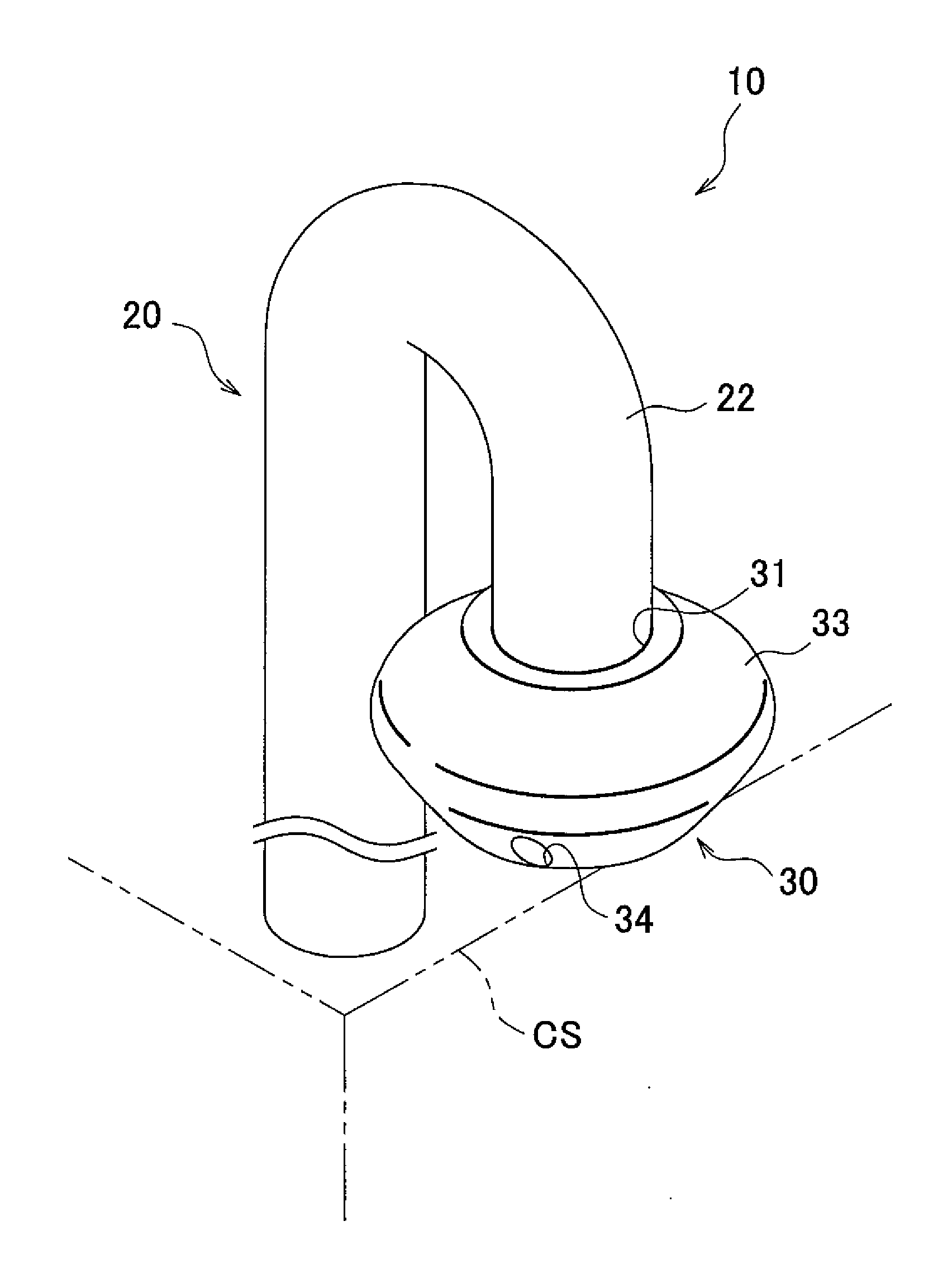
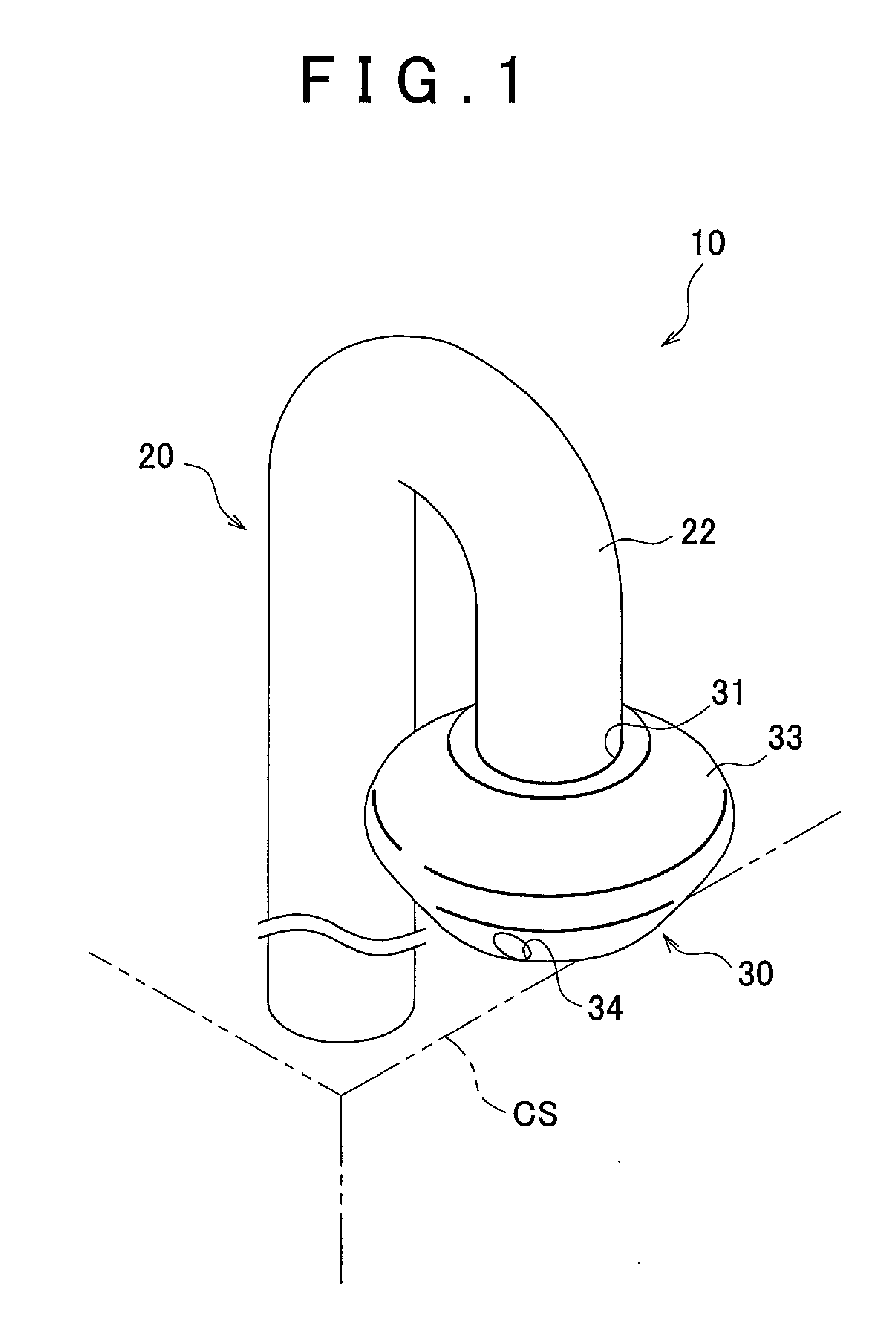
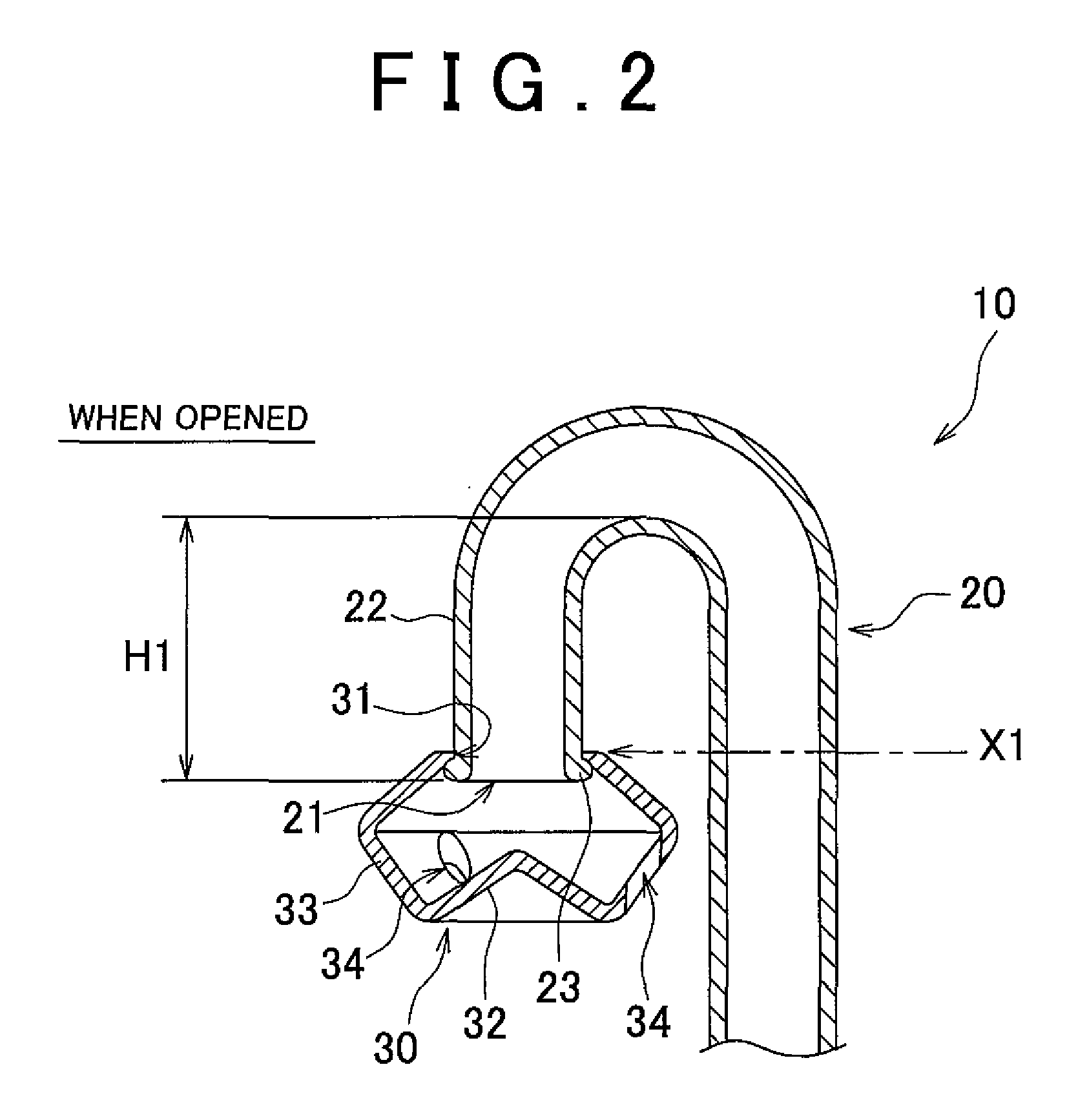
[0038]FIG. 1 is a perspective view showing a breather device in accordance with the FIG. 2 is a sectional view of the breather device of FIG. 1 when the valve mechanism is open. FIG. 3 is a sectional view of the breather device of FIG. 1 when the valve mechanism is closed.
[0039]As shown in FIGS. 1 to 3, a breather device 10 of the first embodiment includes a hose 20 and a cover 30.
[0040]The hose 20 is connected to a transmission case CS. A first end of the hose 20 is provided with an inlet / outlet port 21, and open to the atmosphere. A second end of the hose 20 extends to the transmission case CS, and is in communication with the interior of the transmission case CS. The inlet / outlet port 21 at the first end of the hose 20 is open downward. Here, the flow path for ventilation from the transmission case CS to the inlet / outlet port 21, in other words, the internal space of the hose 20, may correspond to the “breather path” of the invention.
[0041]A portion 22 of the hose 20 on the firs...
second embodiment
[0055]FIG. 4 is a perspective view showing a breather device in accordance with the invention. FIG. 5 is a sectional view of the breather device of FIG. 4 showing the state where the valve mechanism is opened. FIG. 6 is a sectional view of the breather device of FIG. 4 showing the state where the valve mechanism is closed.
[0056]As shown in FIGS. 4 to 6, a breather device 110 of the second embodiment includes a hose 120 and a casing 130.
[0057]The hose 120 is connected to a transmission case CS and the casing 130. A first end of the hose 120 extends to the casing 130, and is in communication with the inside of the casing 130. A second end of the hose 120 extends to the transmission case CS, and is in communication with the inside of the transmission case CS. In FIG. 4, the transmission case CS is not shown, and only a part of the hose 120 on the first end side is shown.
[0058]The casing 130 includes a main body 131 in the shape of a box which is open downward, and a rectangular partiti...
PUM
 Abstract
Description
Claims
Application Information
 - R&D
- Intellectual Property
- Life Sciences
- Materials
- Tech Scout
- Unparalleled Data Quality
- Higher Quality Content
- 60% Fewer Hallucinations
Browse by: Latest US Patents, China's latest patents, Technical Efficacy Thesaurus, Application Domain, Technology Topic, Popular Technical Reports.
© 2025 PatSnap. All rights reserved.Legal|Privacy policy|Modern Slavery Act Transparency Statement|Sitemap|About US| Contact US: help@patsnap.com