
Method and apparatus for determining the thermal neutron capture cross-section of a subsurface formation from a borehole

a technology of thermal neutron capture and subsurface formation, which is applied in the field of oil well logging, can solve the problems of significant noise and limited desired spectral data, and achieve the effect of reducing the number of wells

Inactive Publication Date: 2008-07-03
BAKER HUGHES HLDG LLC
View PDF7 Cites 3 Cited by
  • Summary
  • Abstract
  • Description
  • Claims
  • Application Information

AI Technical Summary

Benefits of technology

This approach enhances the accuracy of neutron capture cross-section measurements by excluding noisy data points, providing a clearer representation of formation properties while avoiding borehole interference, thus improving the reliability of hydrocarbon exploration data.

Problems solved by technology

Moreover, this desired spectral data may not only be limited to that of natural gamma rays, but also may be desired for the gamma ray spectra caused by bombardment of the formation with the aforementioned pulsed neutron sources.
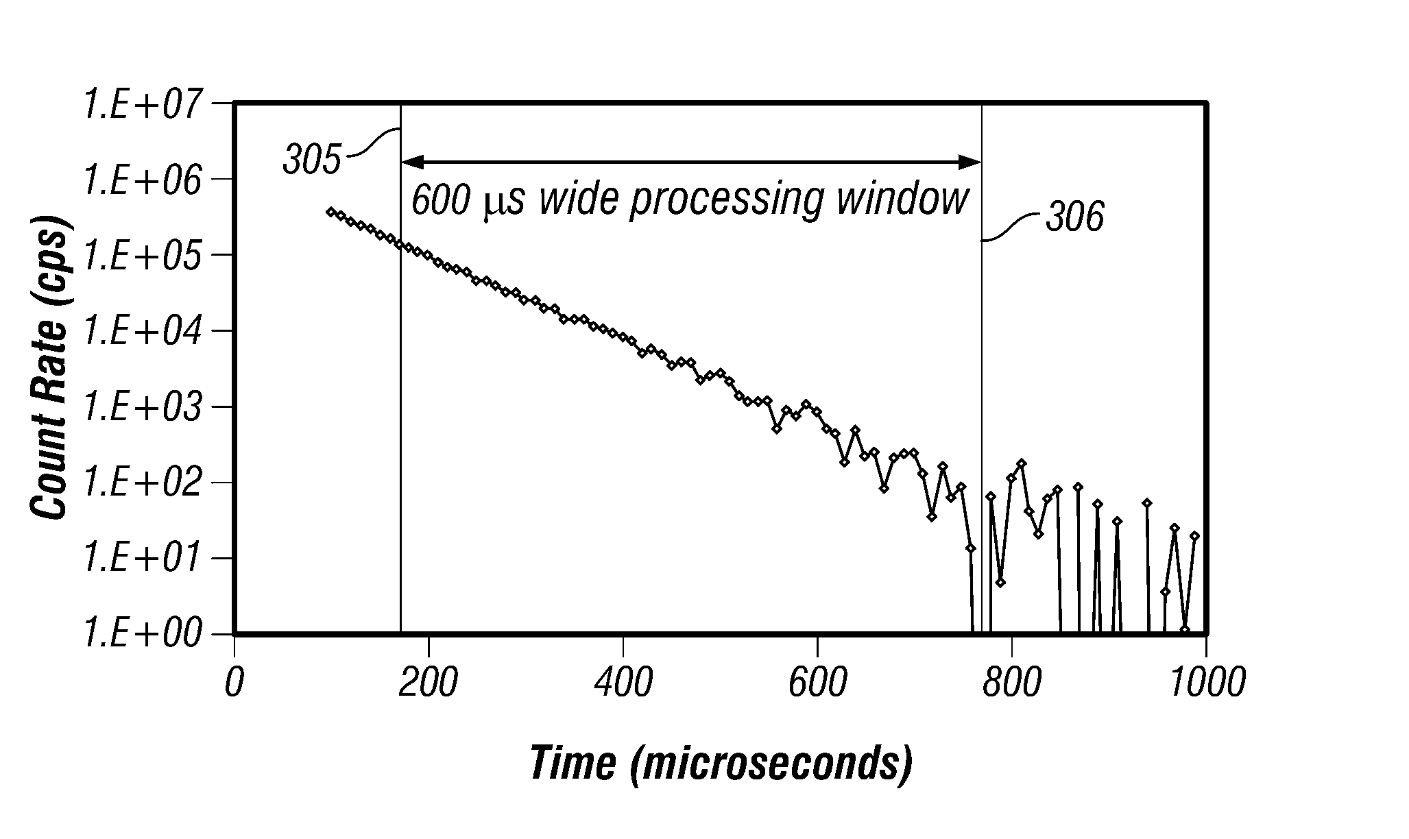
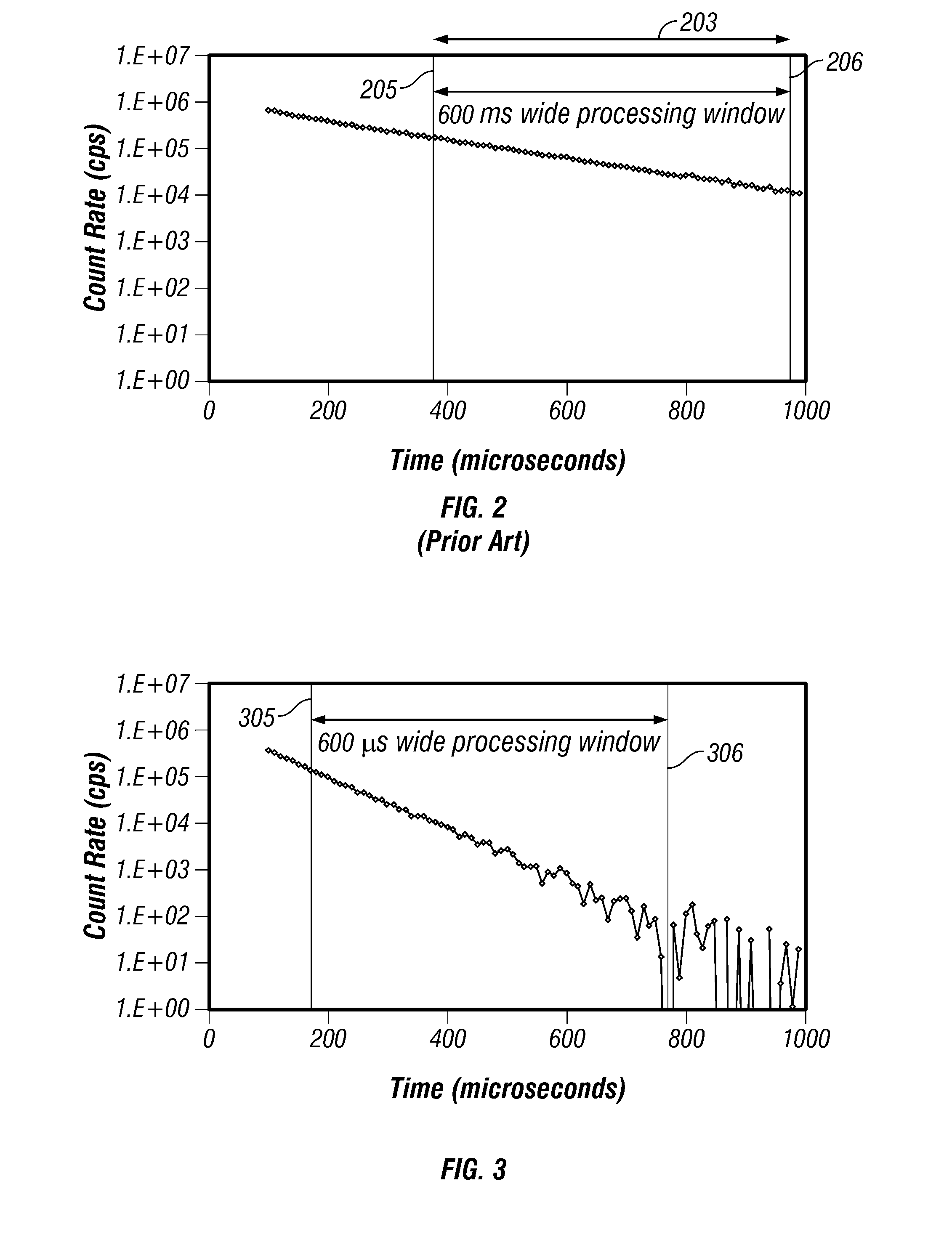
Although positioning an acquisition window can remove the effect of noisy data points from subsequent calculation, significant noise can still be introduced.

Method used


Image

  • Method and apparatus for determining the thermal neutron capture cross-section of a subsurface formation from a borehole
  • Method and apparatus for determining the thermal neutron capture cross-section of a subsurface formation from a borehole
  • Method and apparatus for determining the thermal neutron capture cross-section of a subsurface formation from a borehole

Examples


Embodiment Construction

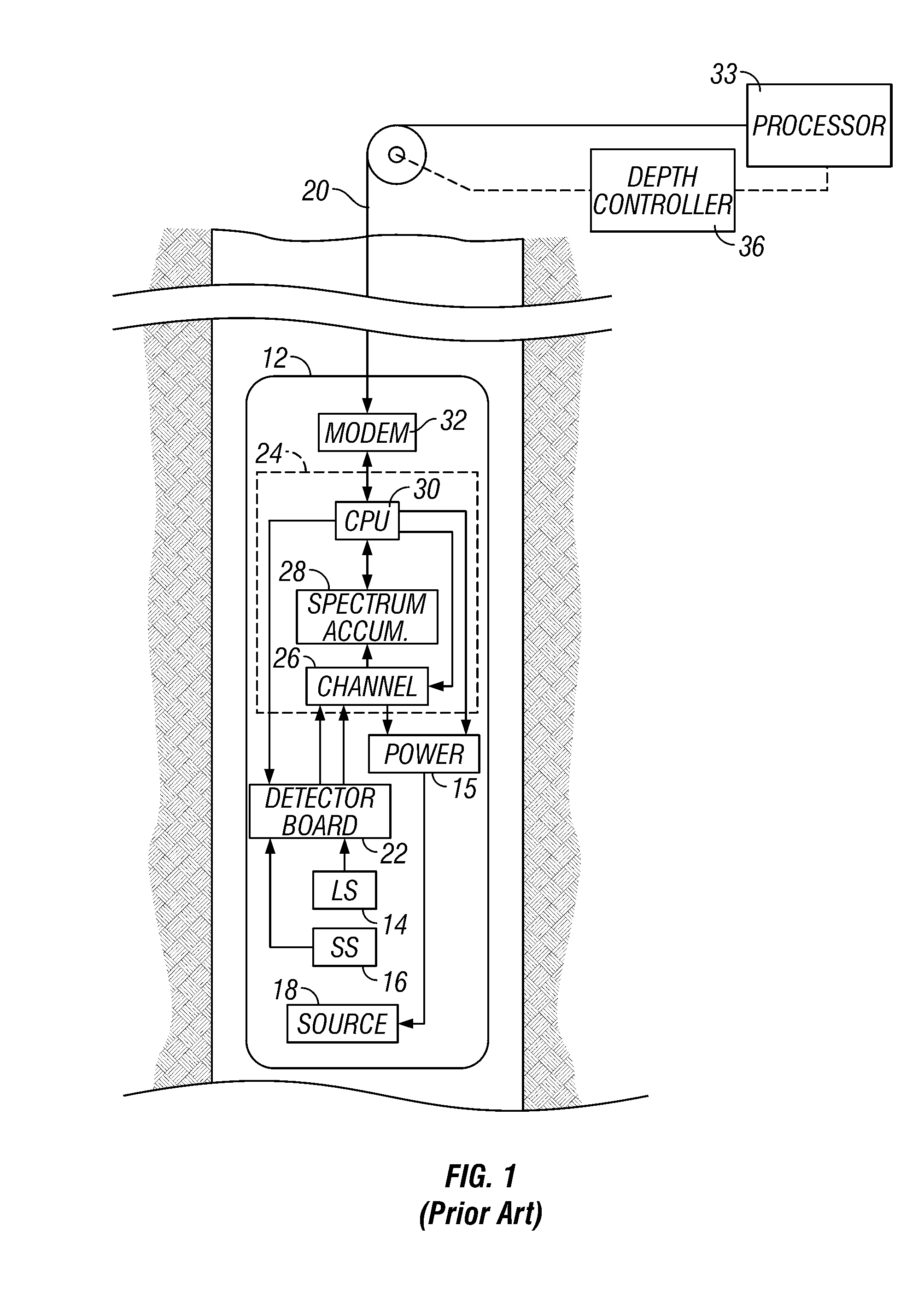
[0023]Referring now to FIG. 1, there is illustrated a nuclear well logging apparatus suitable for use with one embodiment of the present invention. This particular configuration is an example of prior art that could be used and is not intended to be a limitation, and there are other arrangements that could be used. For example, many of the functions that are described herein as being done by electronic circuitry could also be performed by a suitable microprocessor.

[0024]Well 10, also called a borehole, penetrates the earth's surface and may or may not be cased depending upon the particular well being investigated. Disposed within well 10 is subsurface well logging instrument 12. The system diagramed in FIG. 1 is a microprocessor-based nuclear well logging system using multi-channel scale analysis for determining the timing distributions of the detected gamma rays. Well logging instrument 12 includes long-spaced (LS) detector 14, short-spaced (SS) detector 16 and pulsed neutron sourc...


PUM


Abstract

Data acquired using a pulsed nuclear source are susceptible to two sources of error. One error is due to large statistical noise towards the end of an acquisition window. Another source of error is the contamination of the early portion of the data by borehole and other effects. The beginning of the processing window is adjusted based on the signal level at the end of the processing window for the preceding pulsing of the source. The end of the processing window is derived from statistical considerations.

Description

CROSS REFERENCES TO RELATED APPLICATIONS[0001]This application is a continuation of U.S. patent application Ser. No. 10 / 730,552, filed on Dec. 8, 2003, now U.S. Pat. No. 7,166,834.BACKGROUND OF THE INVENTION[0002]1. Field of the Invention[0003]The present invention is related to the field of oil well logging. More specifically, it relates to improved techniques for data acquisition in induced gamma ray logging methods.[0004]2. Description of the Related Art[0005]Well logging systems have been utilized in hydrocarbon exploration for many years. Such systems provide data for use by geologists and petroleum engineers in making many determinations pertinent to hydrocarbon exploration. In particular, these systems provide data for subsurface structural mapping, defining the lithology of subsurface formations, identifying hydrocarbon-productive zones and interpreting reservoir characteristics and contents. Many types of well logging systems exist which measure different formation paramete...

Claims


Application Information

Patent Timeline
Patent Type & Authority Applications(United States)
IPC IPC(8): G01V5/08G01V5/10
CPCG01V5/105G01V5/102
Inventor GILCHRIST, W. ALLENWALSER, RANDOLPH J.
Owner BAKER HUGHES HLDG LLC
Learn More