Ink jet recording apparatus, ink supplying mechanism and ink supplying method

a technology of ink jet recording and ink supply, which is applied in the direction of printing, etc., can solve the problems of difficult to secure a desired flow rate, and difficult to adjust the heigh

Active Publication Date: 2008-07-03
TOSHIBA TEC KK
View PDF8 Cites 89 Cited by
  • Summary
  • Abstract
  • Description
  • Claims
  • Application Information

AI Technical Summary

Problems solved by technology

However, usually, since an arrangement of tanks is often physically limited, it is difficult to adjust the heights.
Further, since the channel resistance changes according to the change of the difference between the heights, it is difficult to secure a desired flow rate.
Consequently, the physical limitation on the arrangement of tanks and the change of channel lengths make it difficult to adjust the heights.

Method used


Image

  • Ink jet recording apparatus, ink supplying mechanism and ink supplying method
  • Ink jet recording apparatus, ink supplying mechanism and ink supplying method
  • Ink jet recording apparatus, ink supplying mechanism and ink supplying method

Examples


first embodiment

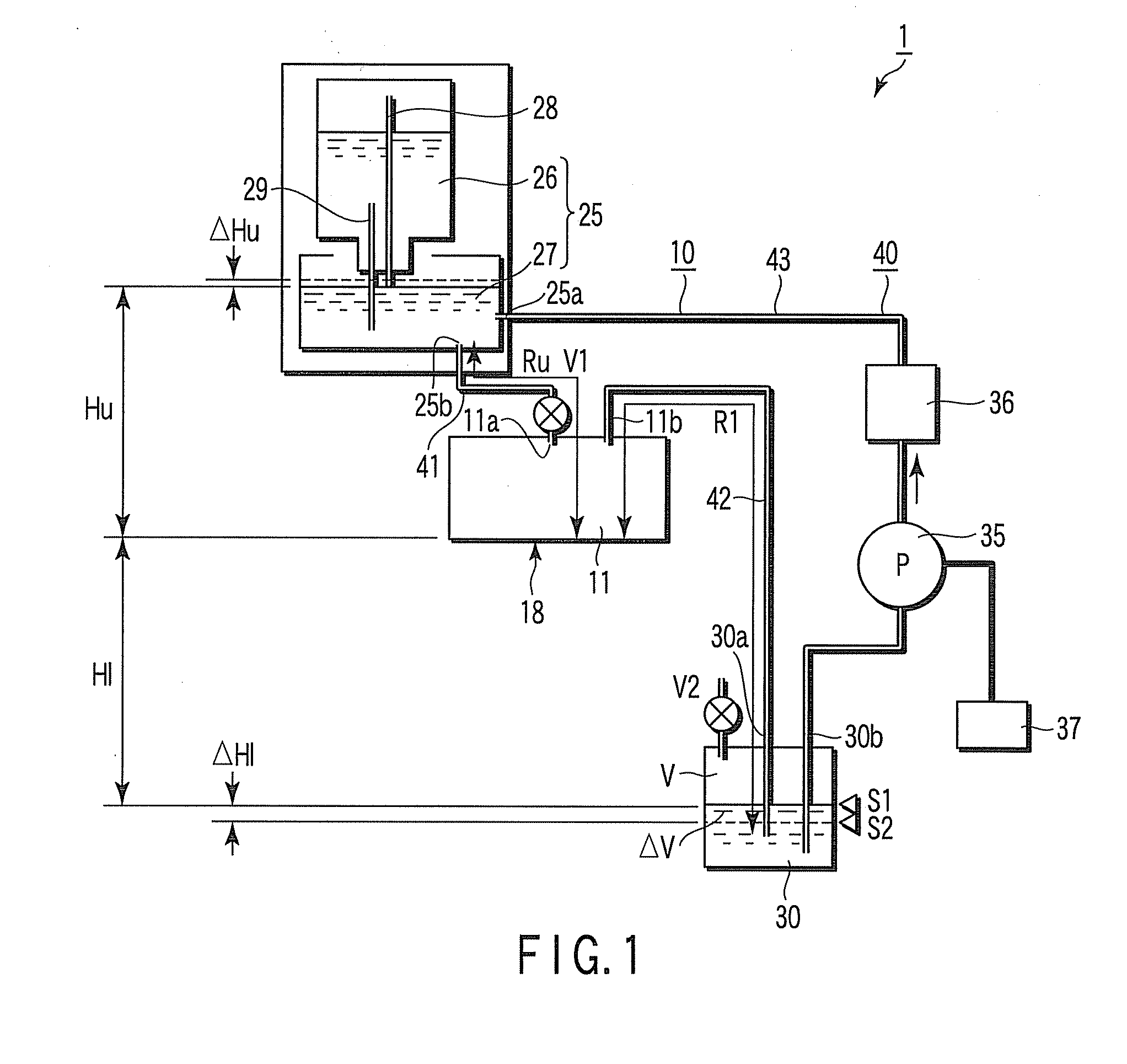
[0030]An ink jet recording apparatus and an ink supplying method according to an embodiment of the invention will be hereinafter explained with reference to FIGS. 1 and 2. In the figures, components are schematically shown by enlarging, reducing, or simplifying the components as appropriate. An ink jet recording apparatus 1 forms an image by ejecting an ink on a not-shown recording medium from a nozzle 17 of an ink jet head 11 while circulating the ink. The ink jet recording apparatus 1 includes an ink supplying mechanism 10. The ink supplying mechanism 10 includes the ink jet head 11, an upstream side tank 25 serving as an ink supply source, a downstream side tank 30 that stores the ink, a first conduit 41, a second conduit 42, and a third conduit 43 that connect the ink jet head 11, the upstream side tank 25, and the downstream side tank 30 and form a circulation path for the ink, a circulating pump 35 serving as an ink sending mechanism that circulates the ink, and a filter 36.

[0...

second embodiment

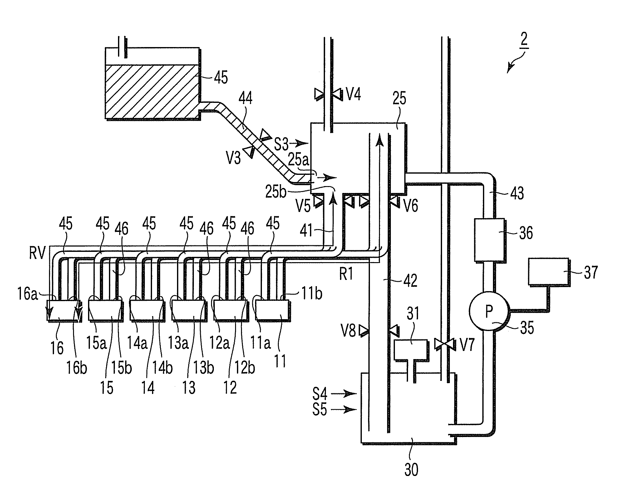
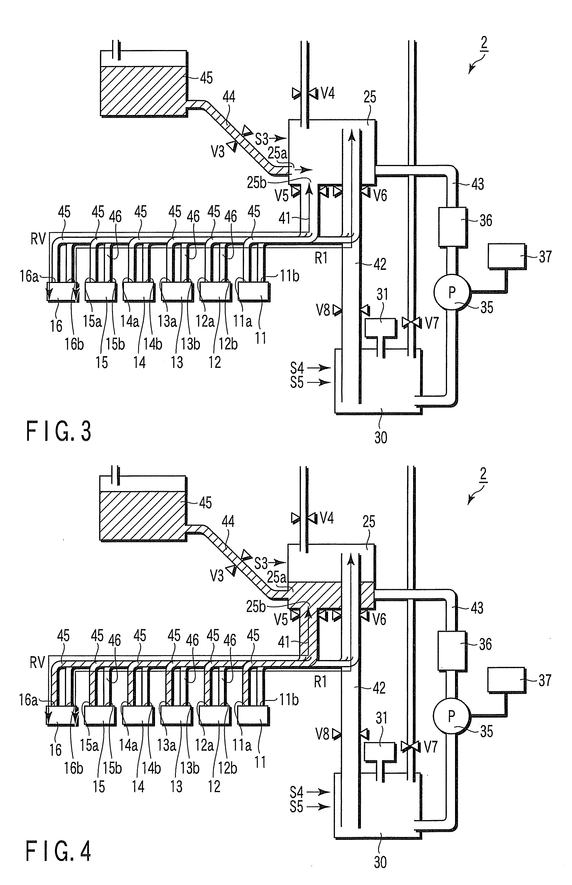
[0061]An ink jet recording apparatus 2 according to a second embodiment of the invention will be explained with reference to FIGS. 3 to 10. In the figures, components are schematically shown by enlarging, reducing, or simplifying the components as appropriate. Explanations of components same as those in the first embodiment are omitted.

[0062]The ink jet recording apparatus 2 shown in FIG. 3 includes plural ink jet heads 11 to 16, the upstream side tank 25 serving as an ink supply source, the downstream side tank 30 that stores an ink, and a supply tank 45 that supplies the ink to the upstream side tank 25.

[0063]The plural (six) ink jet heads 11 to 16 have the same structure as the ink jet head 11 according to the first embodiment.

[0064]The upstream side tank 25 and the supply tank 45 are connected via a fourth conduit 44 that has a valve V3, which is capable of opening and closing a circulation path, in the middle. The supply tank 45 is located above the upstream side tank 25 and th...

third embodiment

[0099]An ink jet recording apparatus according to a third embodiment of the invention will be explained with reference to FIGS. 11 to 16. Explanations of components same as those in the first embodiment or the second embodiment are omitted. In the figures, components are schematically shown by enlarging, reducing, or simplifying the components as appropriate.

[0100]The ink jet recording apparatus 3 shown in FIG. 11 includes the ink jet head 11, the upstream side tank 25 that stores an ink supplied to the ink jet head 11, the downstream side tank 30 that stores the ink, the supply tank 45 that supplies the ink to the downstream side tank 30, the conduits 41 to 44 that form a circulation path for the ink, and the circulating pump 35 serving as an ink sending mechanism that circulates the ink.

[0101]The ink jet head 11 has the same structure as the ink jet head 11 according to the first embodiment.

[0102]Both the upstream side tank 25 and the downstream side tank 30 are arranged lower tha...


PUM


Abstract

An ink supplying mechanism includes a circulating system that connects an ink jet head having a nozzle, a pressure chamber opposed to the nozzle, and an upstream port and a downstream port that communicate with the pressure chamber, an upstream side tank that communicates with the ink jet head via the upstream port and is capable of storing an ink, a downstream side tank that communicates with the ink jet head via the downstream port and is capable of storing the ink, and a circulating pump that feeds the ink from the downstream side tank back to the upstream side tank. The ink supplying mechanism has a relief valve that is capable of opening and closing at least a liquid surface of the downstream side tank with respect to the atmospheric pressure, closes the relief valve to drive the circulating pump, sets the liquid surface of the downstream side tank to a negative pressure, and feeds the ink from the downstream side tank back to the upstream side tank via a feedback channel to circulate the ink.

Description

BACKGROUND OF THE INVENTION[0001]1. Field of the Invention[0002]The present invention relates to an ink jet recording apparatus, an ink supplying mechanism, and an ink supplying method for ejecting an ink from an ink jet head while circulating the ink.[0003]2. Description of the Related Art[0004]A technique for ejecting an ink from a nozzle of an ink jet head while circulating the ink in an ink jet recording apparatus is disclosed in, for example, JP-T-2002-533247 (the term “JP-T” as used herein means a published Japanese translation of a PCT patent application) or US 2002 / 0118256A1. In such an ink jet recording apparatus, for example, an upstream side tank, an ink jet head, and a downstream side tank are connected by a conduit. A liquid surface of the upstream side tank 25 and a liquid surface of the downstream side tank are kept constant. An ink in the upstream side tank circulates to flow into the ink jet head through an upstream side channel and flow into the downstream side tan...

Claims


Application Information

Patent Timeline
Patent Type & Authority Applications(United States)
IPC IPC(8): B41J2/175
CPCB41J2/17596B41J2/175
Inventor NITTA, NOBORUSHIMOSATO, MASASHINISHIDA, HIDEAKISUZUKI, ISAO
Owner TOSHIBA TEC KK
Why Eureka
Try Eureka