Heat dissipating module

a technology of heat dissipation module and heat dissipation module, which is applied in the direction of fluid heaters, air heaters, light and heating apparatus, etc., can solve the problems of high cost, inability to close to the fan, and blocked outside air by the fins, so as to increase the airflow and heat dissipation area, reduce the risk of mold development, and reduce the effect of heat loss

Inactive Publication Date: 2008-07-03
PORTWELL
View PDF7 Cites 9 Cited by
  • Summary
  • Abstract
  • Description
  • Claims
  • Application Information

AI Technical Summary

Benefits of technology

[0006]Therefore, it is a primary objective of the present invention to provide a heat dissipating module applied to a low-level chip for dissipating the heat produced by the low-level chip. The heat dissipating module has a base, and the base has a recession for accommodating a fan, and the base includes first and second fin modules, and the first and second fin modules are comprised of a plurality of unidirectional fins. The first heat dissipating module is installed separately at two corresponding ends of the base, and the second fin module is disposed within the first fin module, and the fins on the second fin module are arranged in an outwardly ascending shape, and the fins at the farthest distance from the fan are bent inwardly. The invention not only allows outside air to enter into the base through the outwardly ascending fins without being blocked, but also increases a heat dissipating area.
[0007]Another objective of the present invention is to provide a heat dissipating module, wherein the fins disposed on the second fin module and at the farthest distance from the fan are bent inwardly, such that when the heat dissipating module is in use, the airflow is blocked by the rotating fan and bounced back to the inner layer of fins, so as to increase the airflow and the heat dissipating area.
[0008]A further objective of the present invention is to provide a heat dissipating module, wherein the height of the fan is not greater than the height of the fin disposed at the farthest end of the second fin module, and thus the invention can increase the airflow and the heat dissipating area while maintaining a small size and volume of the heat dissipating module.

Problems solved by technology

Therefore, the radiating angle will be the same as the direction of the airflow, and the airflow produced by the fan cannot flow among the fins successfully, and outside air is also blocked by the fins and cannot get close to the fan.
Furthermore, the heat dissipating base 100 is shaped by a die casting method, and the development of molds incurs a high cost, and thus the cost is high and the heat dissipating effect is low for the applications of these conventional heat sinks.

Method used


Image

  • Heat dissipating module
  • Heat dissipating module
  • Heat dissipating module

Examples


Embodiment Construction

[0014]To make it easier for our examiner to understand the technical characteristics of the invention, we use preferred embodiments together with the attached drawings for the detailed description of the invention.

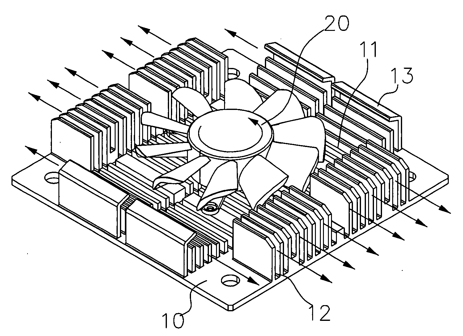
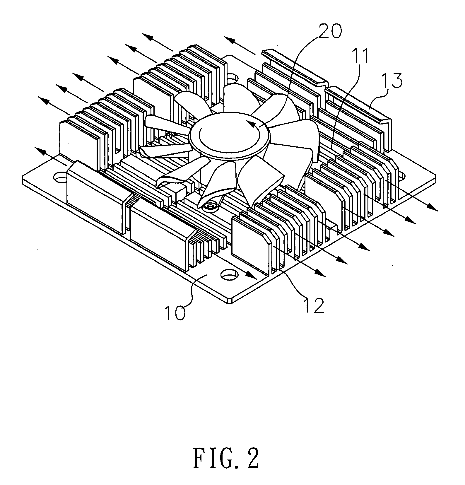
[0015]Referring to FIGS. 2 to 4 for a heat dissipating module in accordance with the present invention, the heat dissipating module is applied to a low-level chip (such as a multimedia processor, a Southbridge chip and a Northbridge chip, etc) for dissipating the heat produced by the low-level chip, and the heat dissipating module has a base 10 made by an aluminum extrusion process, and the base 10 in this embodiment is a rectangular base. The base 10 has a recession 11, and the surface of the recession 11 has a plurality of protrusions for increasing the heat dissipating area, and the recession 11 is provided for precisely containing a fan 20, and two corresponding edges of the base 10 separately have a first fin module 12, and the first fin module 12 is comprised of orde...


PUM


Abstract

The present invention discloses a heat dissipating module applied to a low-level chip for dissipating the heat produced by the low-level chip. The heat dissipating module has a base, and the base accommodates a fan. The base includes first and second fin modules, and the first and second fin modules are comprised of a plurality of unidirectional fins. The first heat dissipating module is installed separately at two corresponding ends of the base, and the second fin module is disposed within the first fin module, and the fins on the second fin module are arranged in an outwardly ascending shape, and the fins at the farthest distance from the fan are bent inwardly. The invention not only allows outside air to enter into the base through the outwardly ascending fins without being blocked by the fins adjacent to the fan, but also increases the heat dissipating area.

Description

BACKGROUND OF THE INVENTION[0001]1. Field of the Invention[0002]The present invention relates to a heat dissipating module assembly, and more particularly to a heat dissipating module having first and second fin modules comprised of a plurality of unidirectional fins disposed on a base of the heat dissipating module, and the second fin module is situated within the first fin module, and the fins of the second fin module are arranged in an outwardly ascending shape, and the fins far apart from the fan are inwardly bent, so as to increase the airflow and the heat dissipating area.[0003]2. Description of the Related Art[0004]In general, a conventional heat sink for a low-level chip (such as a multimedia processor, a Southbridge chip and a Northbridge chip, etc) as shown in FIG. 1 includes a heat dissipating base 100, and the heat dissipating base 100 has a seat 101, and the seat 101 has a plurality of orderly arranged and integrally formed fins 102, such that when the fan 103 is instal...

Claims


Application Information

Patent Timeline
Patent Type & Authority Applications(United States)
IPC IPC(8): H05K7/20
CPCH01L23/467H01L2924/0002H01L2924/00
Inventor HUNG, TE-FU
Owner PORTWELL
Why Eureka
Try Eureka