Flip-chip packaging structure for light emitting diode and method thereof

a technology of light-emitting diodes and packaging structures, which is applied in the direction of transportation and packaging, basic electric elements, metal working apparatuses, etc., can solve the problems of increasing the heat produced by leds, shortening the operation life of leds, and damage to leds themselves, so as to increase the brightness and heat dissipation efficiency of leds, and increase the contact area. , the effect of increasing the heat dissipation efficiency

Active Publication Date: 2008-08-05
EPISTAR CORP
View PDF5 Cites 7 Cited by
  • Summary
  • Abstract
  • Description
  • Claims
  • Application Information

AI Technical Summary

Benefits of technology

[0007]In order to increase LED brightness and heat dissipating efficiency simultaneously, the present invention provides a flip-chip packaging structure and a related method which use eutectic bonding to attach a LED to a thermal conducting substrate. The flip-chip packaging structure and the method of the present invention avoid blocking the light emitted from the LED, and rely on a larger contact area and higher thermal conductivity to conduct heat to a thermal conducting substrate for efficient heat dissipation.
[0009]In contrast to the prior arts, the LED packaged by the present invention does not have its light blocked by the electrodes and therefore has better brightness. The heat produced by the LED can also be conducted more efficiently via the eutectic layer which has a much larger contact area between the thermal conducting substrate and the LED, instead of, as in the prior arts, going through the sapphire substrate of the LED which has inferior thermal conductivity. Therefore, the heat generated by the LED can be conducted and dissipated to the thermal conducting substrate more effectively and efficiently.

Problems solved by technology

These will inevitably increase the heat produced by the LEDs.
This heat, if not effectively dissipated, will damage the LEDs themselves, shorten their operation life, and affect their brightness.
In this conventional approach, even though the eutectic layer 30 is able to dissipate the heat produced by the LED 10 through the aluminum substrate 20 by conduction, the sapphire substrate 13 of the LED 10 has inferior thermal conductivity and the heat dissipation efficiency is therefore impaired.
Additionally, the PCB 40 itself has limited thermal conductivity and cannot provide satisfactory help to the heat dissipation.

Method used


Image

  • Flip-chip packaging structure for light emitting diode and method thereof
  • Flip-chip packaging structure for light emitting diode and method thereof
  • Flip-chip packaging structure for light emitting diode and method thereof

Examples


Embodiment Construction

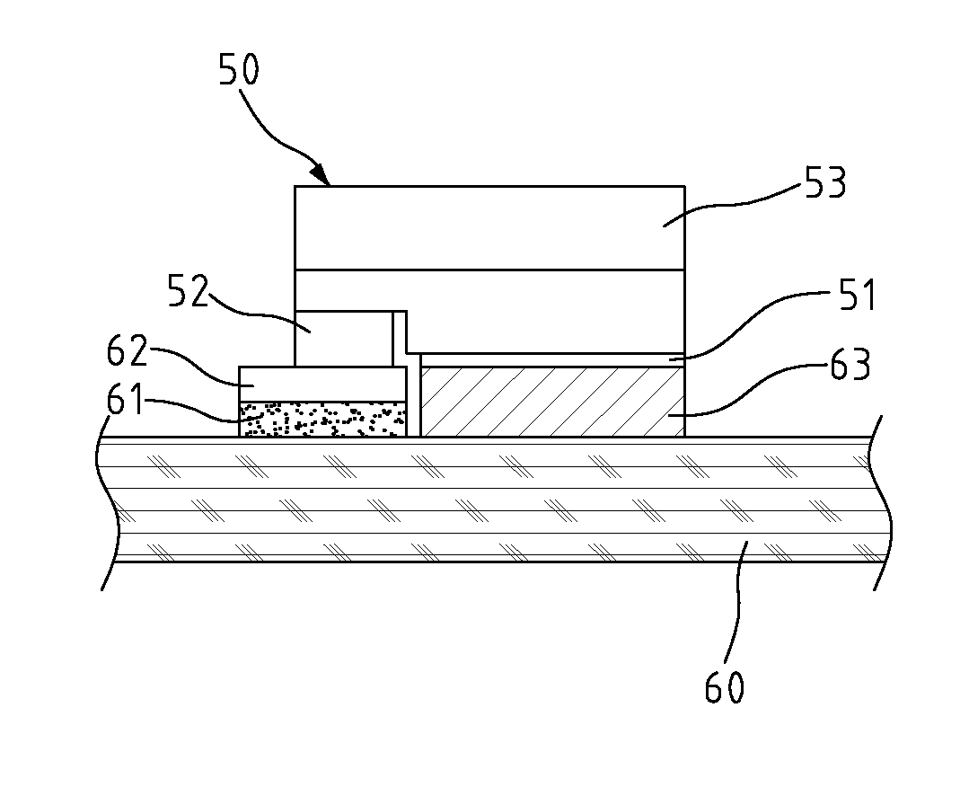
[0016]With reference to the drawings and in particular to FIG. 3, FIG. 3 is a schematic view according to an embodiment of the present invention. As illustrated, the flip-chip packaging structure comprises a LED 50 and a thermal conducting substrate 60, bonded together by a flip-chip technology.

[0017]LED 50 comprises a first electrode 51 and a second electrode 52, where the first and second electrodes 51 and 52 are provided on a same side of the LED 50. The first and second electrodes 51 and 52 are made of metals like Ti, Al, or Au formed by physical vapor deposition (PVD) and fusing. For a GaN-based LED die, the first electrode 51 can be joined with the P− GaN layer and functions as the p-type electrode, and the second electrode 52 can be joined with the n+ GaN layer and functions as the n-type electrode. Please note that this arrangement of electrodes is exemplary only and there are various other alternatives. Also, during the vapor deposition process, the first electrode 51 can b...


PUM


Abstract

A packaging structure and method for a light emitting diode is provided. The present invention uses flip-chip and eutectic bonding technology to attach a LED to a thermal and electrical conducting substrate. The flip-chip packaging structure comprises a thermal and electrical conducting substrate having an insulating layer formed in an appropriate area on the top surface of the substrate and a bonding pad formed on top of the insulating layer; and a LED reversed in a flip-chip style and joined to the substrate by eutectic bonding. A first electrode of the LED is eutectically bonded to an appropriate area on the top surface of the substrate via a eutectic layer, while a second electrode of the LED is electrically connected to the bonding pad.

Description

BACKGROUND OF THE INVENTION[0001]1. Field of the Invention[0002]The present invention generally relates to packaging structures for light emitting diodes, and more particularly to a flip-chip packaging structure and a related method for light emitting diodes with enhanced heat dissipating efficiency.[0003]2. The Prior Arts[0004]Light emitting diodes (LEDs) have advantages of small size, low power consumption, long operation life, and therefore will substitute light bulbs or fluorescent lamps in the future as the mainstream light source. However, to enhance the brightness of LEDs, it is necessary to increase power, numbers, or density of LEDs. These will inevitably increase the heat produced by the LEDs. This heat, if not effectively dissipated, will damage the LEDs themselves, shorten their operation life, and affect their brightness.[0005]To improve heat dissipation, a packaging structure as shown in FIG. 1 has been adopted. As illustrated, LED 10 is attached to an aluminum substra...

Claims


Application Information

Patent Timeline
Patent Type & Authority Patents(United States)
IPC IPC(8): H01L29/22H01L23/495H01L33/62
CPCH01L33/62H01L24/92H01L24/83H01L24/73H01L24/32H01L24/29H01L2224/48091H01L2924/12041H01L2224/16225H01L2224/32225H01L2224/81903H01L2224/9211H01L2224/83805H01L2224/83192H01L2224/83101H01L2224/81192H01L2224/73203H01L2224/32506H01L2224/32227H01L2224/29144H01L2224/29124H01L2224/16238H01L2224/131H01L24/81H01L24/16H01L2224/29034H01L2224/32502H01L2224/49107H01L2224/73265H01L2924/01078H01L2924/01079H01L2924/01322H01L2924/01019H01L2924/00014H01L2924/01013H01L2924/00012H01L2224/81H01L2224/83H01L2924/00H01L24/05H01L2224/0554H01L2224/05568H01L2224/05573H01L2224/05624H01L2224/05644H01L2224/05647H01L2224/05666Y10T225/286Y10T225/29Y10T225/298Y10T225/30Y10T225/343H01L2224/05599H01L2224/0555H01L2224/0556
Inventor TUNG, CHING-WEN
Owner EPISTAR CORP
Why Eureka
Try Eureka