Compound type heat exchanger

Inactive Publication Date: 2006-07-18
CALSONIC KANSEI CORP
View PDF7 Cites 8 Cited by
  • Summary
  • Abstract
  • Description
  • Claims
  • Application Information

AI Technical Summary

Benefits of technology

[0005]In the above-mentioned situation, it is an object of the present invention to provide a compound type heat exchanger having a plurality of heat e

Problems solved by technology

In the compound type heat exchanger, however, there is a great difference in temperature between a heat exchanging medium flowing the condenser and oil flowing the oil cooler.
Therefore, there

Method used


Image

  • Compound type heat exchanger
  • Compound type heat exchanger
  • Compound type heat exchanger

Examples


first embodiment

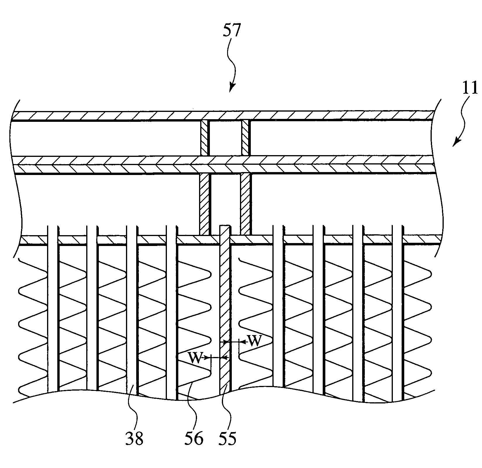
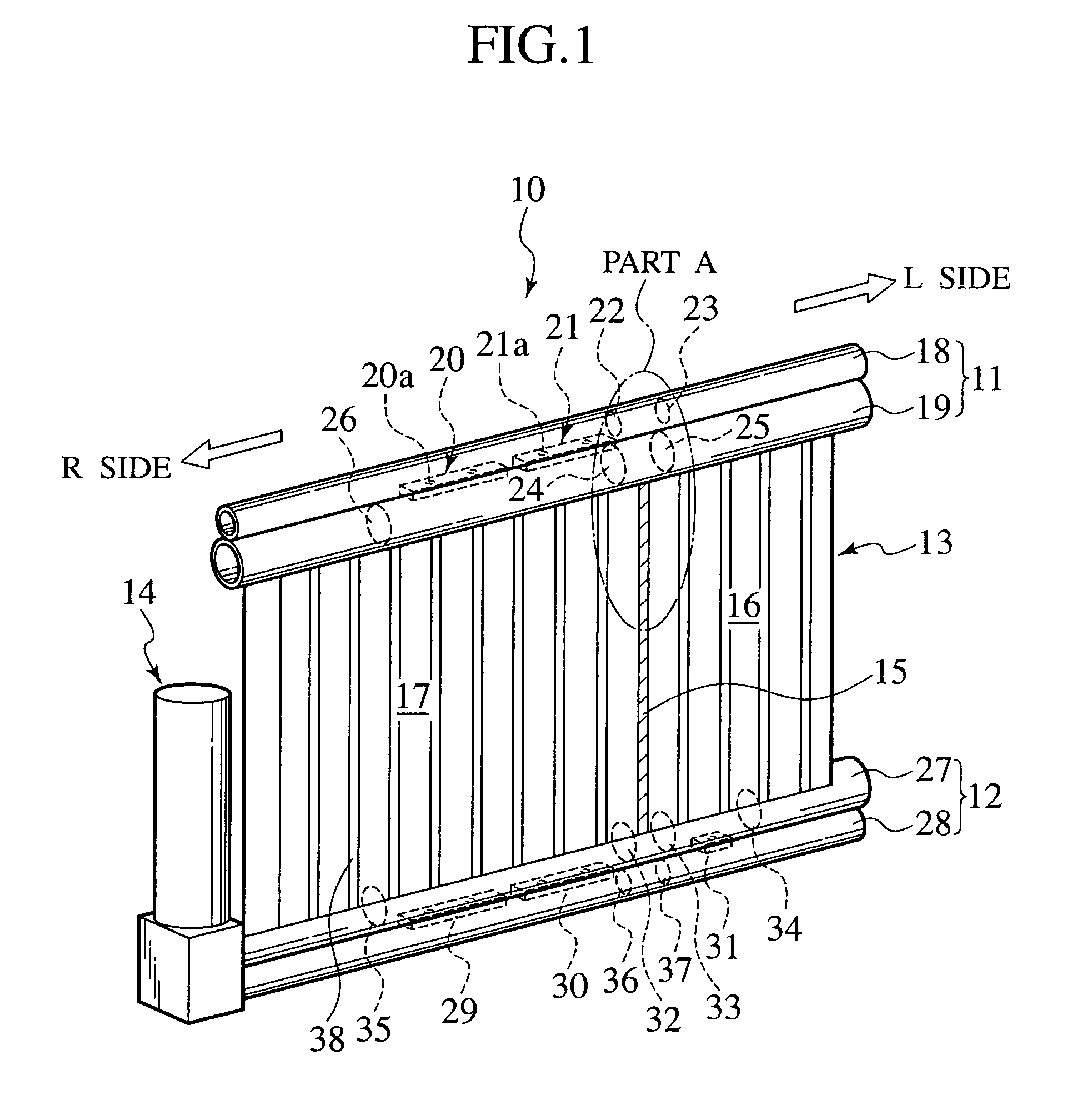
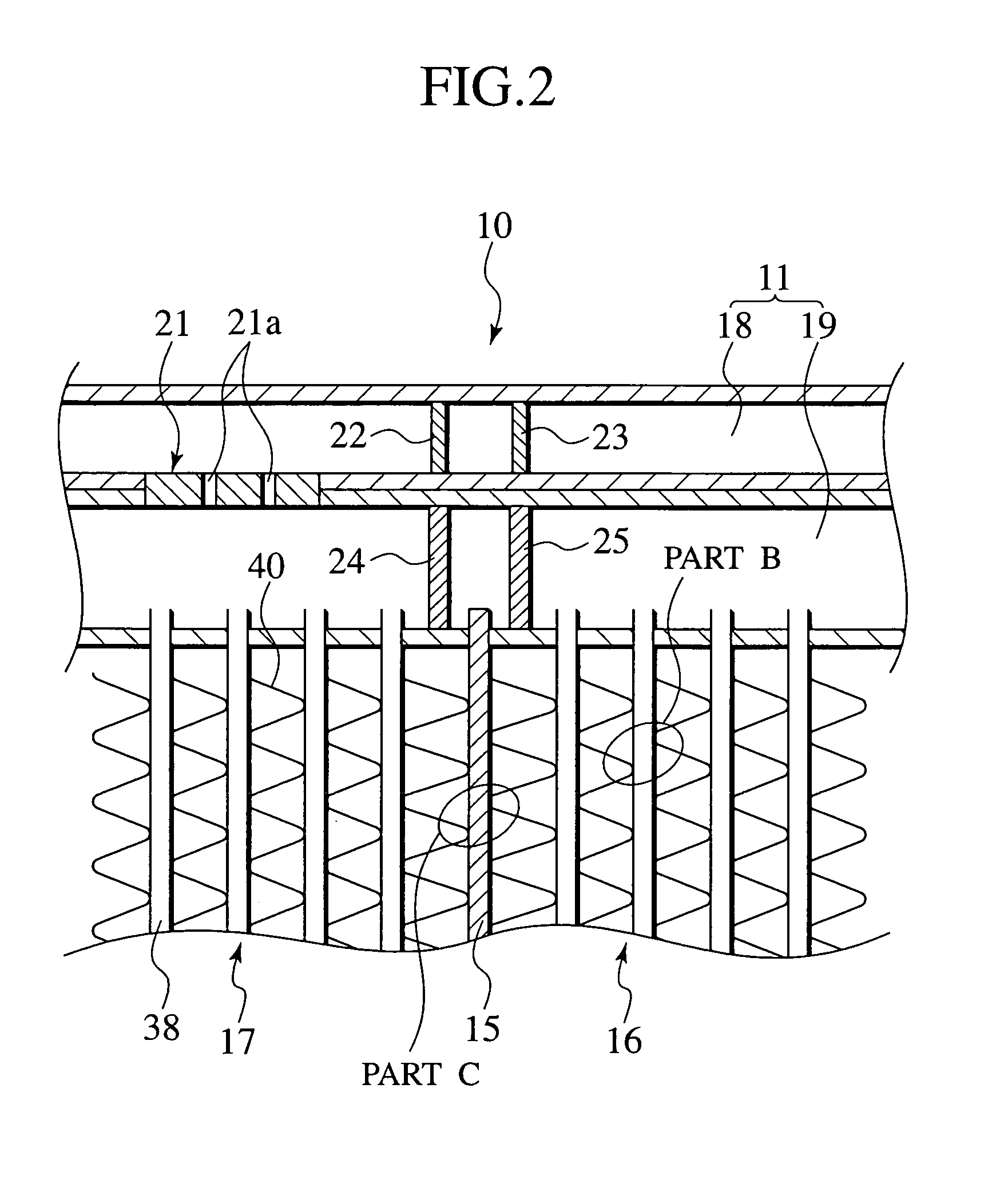
[0033]FIG. 1 is a perspective view of a compound type heat exchanger 10 in accordance with the present invention. As shown in this figure, the heat exchanger 10 of this embodiment includes an upper header pipe 11 on the upper side, a lower header pipe 12 on the lower side, a core part 13 connecting the upper header pipe 11 with the lower header pipe 12 in the vertical direction and a liquid tank 14 connected to the lateral side of the lower header pipe 12. This figure leaves out fins in order to clarify the constitution of the heat exchanger 10. A heat exchanger's part on the left side (“L” side shown in FIG. 1) of a pseudo heat exchanging passage member 15 constitutes an oil cooler unit 16 (as the first heat exchanging unit), while another heat exchanger's part on the right side (“R” side shown in FIG. 1) of the pseudo heat exchanging passage member 15 constitutes a condenser unit 17 (as the second heat exchanging unit). The condenser unit 17 serves to cool a cooling medium for air...

second embodiment

[0049]According to the heat exchanger 45 of the second embodiment, since the fins 40 are not joined to the member's surface (on the side of the condenser unit 17) of the pseudo heat exchanging passage member 44, there is almost no heat conduction from the oil cooler unit 16 of high temperature to the condenser unit 17 of relatively how temperature, whereby the heat exchanging performance of the heat exchanger 10 as a whole can be maintained. Conversely, since the fins 40 are joined to the member's other surface (on the side of the oil cooler unit 16) of the pseudo heat exchanging passage member 44, it is possible to maintain high joint-strength about the fins 40 while suppressing heat conduction from the oil cooler unit 16 of high temperature to the condenser unit 17 of relatively how temperature.

embodiment

3rd. Embodiment

[0050]FIGS. 8 and 9 show the third embodiment of the present invention. In these figures, FIG. 8 shows a heat exchanger 46 of the third embodiment invention. FIG. 9 is a partial view of the heat exchanger 46. Note, also in this embodiment, elements identical to those of the first and second embodiments are respectively indicated with the same reference numerals and their overlapping descriptions are eliminated.

[0051]In the heat exchanger 46 of the second embodiment, the fins 40 are joined to the heat exchanging tubes 38 through cladding layers (not shown in FIG. 8), as similar to the first embodiment. The third embodiment differs from the first embodiment in the fins 40 adjoining a pseudo heat exchanging passage member 47.

[0052]As shown in FIG. 8, the heat exchanger 46 has a condenser unit 17 and an oil cooler unit 16 on both sides of the pseudo heat exchanging passage member 47, similarly to the first embodiment. The fins 40 are joined to the heat exchanging tubes 38...


PUM


Abstract

A compound type heat exchanger has an oil cooler unit and a condenser unit integrated with each other. Both of the units have a plurality of heat exchanging pipes and fins juxtaposed and alternately stacked into a lamination, in common. At both ends of the lamination in the longitudinal direction of the pipes, they are connected with header pipes. At a boundary between the units, the heat exchanger includes partition walls arranged in the header pipes and a pseudo heat exchanging passage member interposed in the lamination. Further, at least either one of two fins adjoining the pseudo heat exchanging passage member on the side of the oil cooler unit and also on the side of the condenser unit is joined to the pseudo heat exchanging passage member, while the other fins are joined to the pipes.

Description

BACKGROUND OF THE INVENTION[0001]The present invention relates to a compound type heat exchanger having a plurality of independent heat exchanging units, such as condenser and oil cooler, integrated with each other.[0002]Normally, an automobile is equipped with some heat exchanging units, for example, a radiator for cooling an engine, an air conditioning condenser, an oil cooler for cooling automatic transmission oil (i.e. ATF oil cooler), an oil cooler for cooling engine oil and so on. Hitherto, the above radiator and the condenser are individually arranged in the front area of an engine. Recently, in view of reducing the installation space of such units for purpose of the downsizing of an engine and also reducing the number of assembling steps of the units, a compound type heat exchanger where a condenser and an oil cooler are integrated in one body has been developed.[0003]In the compound type heat exchanger, however, there is a great difference in temperature between a heat exch...

Claims


Application Information

Patent Timeline
IPC IPC(8): F28F9/02F01P3/18F28D1/04F28F1/12F28F9/26F28F13/00
CPCF28D1/0443F28F1/126F28F13/00F28F2270/00F28F2009/0287
Inventor KAMIYAMA, NAOHISAWATANABE, TOSHIHARU
Owner CALSONIC KANSEI CORP
Why Eureka
Try Eureka