
Image forming apparatus and control method thereof

a technology of image forming apparatus and control method, which is applied in the direction of instruments, electrographic process, sustainable buildings, etc., can solve the problems of insufficient margin and damage to the fixing uni

Active Publication Date: 2008-07-03
HEWLETT PACKARD DEV CO LP
View PDF4 Cites 15 Cited by
  • Summary
  • Abstract
  • Description
  • Claims
  • Application Information

AI Technical Summary

Benefits of technology

[0008]The present general inventive concept provides an image forming apparatus which can detect a malfunction of a unit which supplies an operating voltage to a heat radiation unit, and a control method thereof.
[0009]The present general inventive concept also provides an image forming apparatus which can prevent a fixing unit from being damaged due to high thermal heat or an accident from being caused due to a temperature rise beforehand, and a control method thereof.

Problems solved by technology

If a heat radiating plate for the triac is designed to be large to radiate the heat, the thermal runaway can be prevented beforehand, but frequently a spatial restriction etc., does not allow an enough margin.
Therefore, the fixing unit may be damaged due to the heat from high temperature or other problems may occur due to the temperature rise of the triac.

Method used


Image

  • Image forming apparatus and control method thereof
  • Image forming apparatus and control method thereof
  • Image forming apparatus and control method thereof

Examples


Embodiment Construction

[0040]Reference will now be made in detail to exemplary embodiments of the present general inventive concept, examples of which are illustrated in the accompanying drawings, wherein like reference numerals refer to like elements throughout. The embodiments are described below in order to explain the present general inventive concept by referring to the figures.

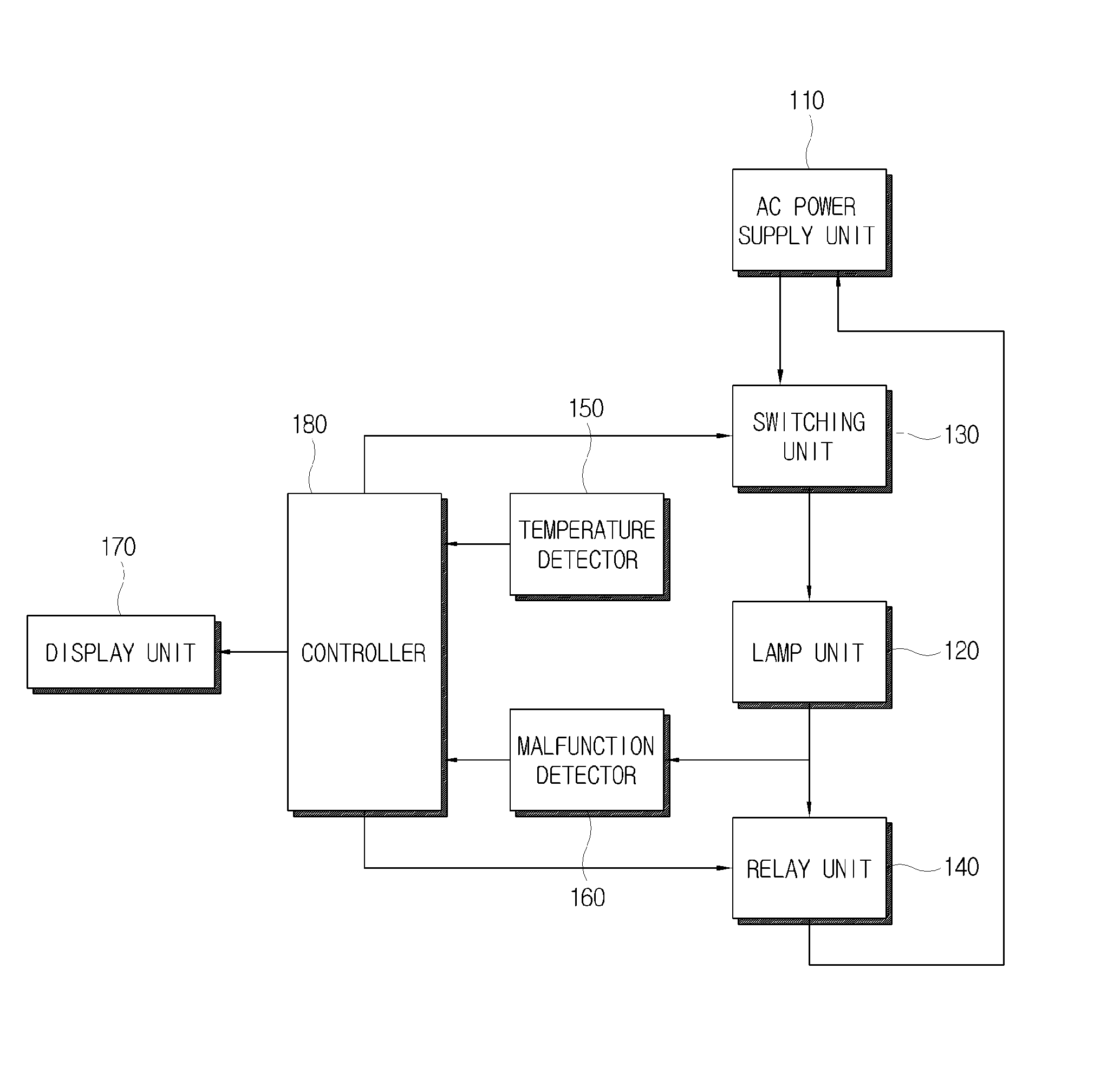
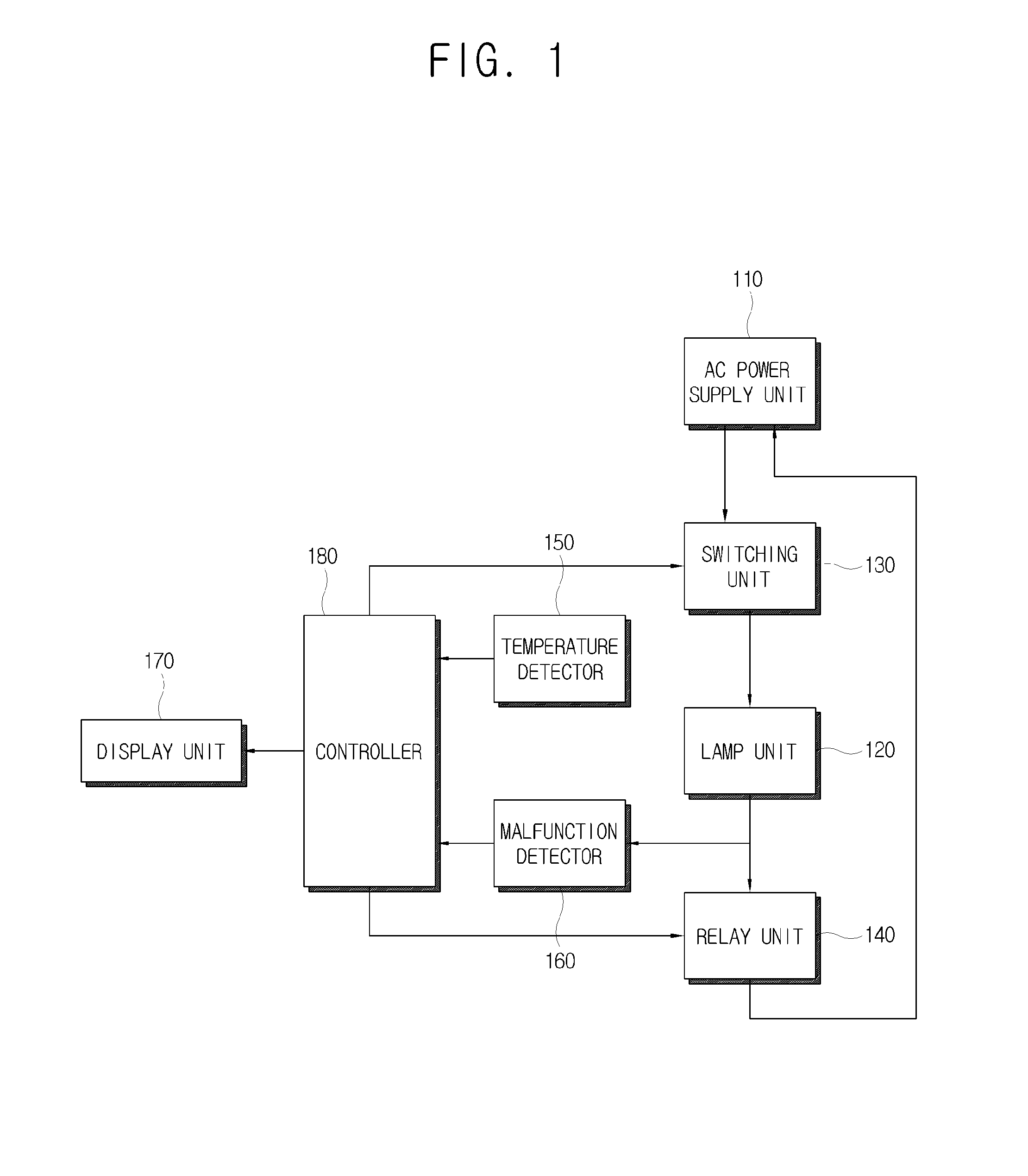
[0041]FIG. 1 is a block diagram illustrating a configuration of an image forming apparatus 100 according to an exemplary embodiment of the present general inventive concept.

[0042]The image forming apparatus 100 illustrated in FIG. 1 includes an alternating-current (AC) power supply unit 110, a lamp unit 120, a switching unit 130, a relay unit 140, a temperature detector 150, a malfunction detector 160, a display unit 170 and a controller 180.

[0043]The AC power supply unit 110 supplies an AC power to the lamp unit 120 of a fixing unit which is described according to an exemplary embodiment of the present general inventive conce...


PUM


Abstract

An image forming apparatus includes a heat radiation unit to emit heat by an operating power supplied to the heat radiation unit, a switching unit to supply the heat radiation unit with the operating power, a relay unit to control the operating power to be supplied to the switching unit, a malfunction detector to detect whether the operating power is being supplied to the heat radiation unit and to output a malfunction signal corresponding to the switching unit or the relay unit if the power is not supplied thereby denoting a malfunction, and a controller to output an off-signal to at least one of the switching unit and the relay unit if the malfunction signal is received from the malfunction detector.

Description

CROSS-REFERENCE TO RELATED APPLICATIONS[0001]This application claims priority under 35 U.S.C. 119(a) from Korean Patent Application No. 10-2006-0138264, filed on Dec. 29, 2006, in the Korean Intellectual Property Office, the disclosure of which is incorporated herein in its entirety by reference.BACKGROUND OF THE INVENTION[0002]1. Field of the Invention[0003]The present general inventive concept relates to an image forming apparatus and a control method thereof, and more particularly, to an image forming apparatus which can detect malfunction of a switching unit or relay unit and a control method thereof.[0004]2. Description of the Related Art[0005]A conventional image forming apparatus that uses an electrophotographic method includes a fixing unit that fixes an image transferred on a printing medium. The fixing unit includes a heating roller, a pressurization roller and a lamp. Therefore, a surface of the heating roller is heated by heat emitted from the lamp, and the image transfe...

Claims


Application Information

Patent Timeline
IPC IPC(8): G03G15/20
CPCG03G15/5004G03G15/55G03G15/80G03G15/2039H05B41/2851H05B41/2858Y02B20/186Y02B20/00G03G15/205G03G15/5012
Inventor PARK, JAE-SUNG
Owner HEWLETT PACKARD DEV CO LP
Learn More