Compressor

a compressor and compression tube technology, applied in the field of compressors, can solve the problems of increasing the production cost of the compressor, increasing the production cost, and the possibility of seizing the compressor, and achieve the effects of compact and inexpensively manufactured compressors, strong circulating magnetic circuits, and cheap manufacturing

Inactive Publication Date: 2008-07-03
TOYOTA BOSHOKU KK
View PDF12 Cites 3 Cited by
  • Summary
  • Abstract
  • Description
  • Claims
  • Application Information

AI Technical Summary

Benefits of technology

[0029]According to the compressor of the present invention, the rotation state of the compressor is detected by providing a permanent magnet on a drain bolt, which is normally provided, in order to form a circulating magnetic circuit via the drain bolt, and by detecting the magnetic flux changes in this circulating magnetic circuit from the outside of the housing member by using a magnetic sensor that is provided at the head portion of the drain bolt. Thereby, it is possible to provide a rotation detecting mechanism by using a pre-existing drain bolt hole, without requiring the machining of a hole in the compressor body in order to provide a detecting device, and it is possible thereby to provide a compact and inexpensively manufactured compressor. In addition, because the detecting device is positioned on the outside of the housing member, it is not necessary to protect the detecting device from pressure. Additionally, because it is possible to avoid the inclusion of contaminants that accompanies the placement of the detecting device, it is possible to provide a compact and inexpensively manufactured compressor.
[0030]In addition, in the case in which a circulating magnetic circuit, which is due to the magnetic flux of a permanent magnet, is conducted through the detected body and the drain bolt, it is possible to form a stronger circulating magnetic circuit, and it is possible thereby to detect the magnetic flux changes in the circulating magnetic circuit more reliably.
[0031]Furthermore, in the case in which the permanent magnet is provided at the distal end of the drain bolt, it is possible to form a stronger circulating magnetic circuit, and it is possible thereby to detect the magnetic flux changes in the circulating magnetic circuit more reliably.
[0032]In addition, in the case in which the permanent magnet is provided at the head portion of the drain bolt, it is possible to form a stronger circulating magnetic circuit, and it is possible thereby to detect the magnetic flux changes in the circulating magnetic circuit more reliably.
[0033]Furthermore, in the case in which the detecting device is provided with a magnetic member that covers the head portion of the drain bolt, it is possible to form a stronger circulating magnetic circuit, and it is possible thereby to detect the magnetic flux changes in the circulating magnetic circuit more reliably.
[0034]According to the compressor of the present invention, the magnetic flux from a magnet that is provided in a detected body forms a circulating magnetic circuit via a drain bolt, and the rotation state of the compressor is detected by detecting the magnetic flux changes in this circulating magnetic circuit from the outside of the housing member by using a magnetic sensor that is provided at the head portion of the drain bolt. Thereby, it is possible to provide a rotation detecting mechanism by using a pre-existing drain bolt hole without requiring the machining of a hole in the compressor body in order to provide the detecting device, and it is possible thereby to provide a compact and inexpensively manufactured compressor. In addition, because the detecting device is positioned on the outside of the housing member, it is not necessary to protect the detecting device from high pressure. Additionally, because it is possible to avoid the inclusion of contaminants that accompanies the placement of the detecting device, it is possible to provide thereby a compact and inexpensively manufactured compressor.

Problems solved by technology

However, in this conventional rotation detecting mechanism, it is necessary to form the through hole 102 by machining a hole in the housing member 101, and the production cost of the compressor is thereby increased.
In addition, a sealing structure that uses the O-ring 103 is necessary, and this further increases the production cost.
Furthermore, there are problems in that, for example, contaminants that adhere to the detecting sensor104 may enter into the compressor, and there is thus the possibility of seizing of the compressor.
JP-A-H6-299960, the magnetic sensor is placed at the head portion of the fastening fixtures or on the stator side of an electromagnetic clutch that is opposite to the fastening fixtures, and there is a problem in that the overall length of the compressor in the axial direction is increased due to the space for the sensor installation.
Furthermore, in order to amplify the magnetic flux, which takes the form of a large circulating magnetic flux circuit, a strong and high cost magnet is necessary.
For these reasons, there is the problem, for example, that the production cost of the compressor is increased.

Method used


Image

  • Compressor
  • Compressor
  • Compressor

Examples


embodiments

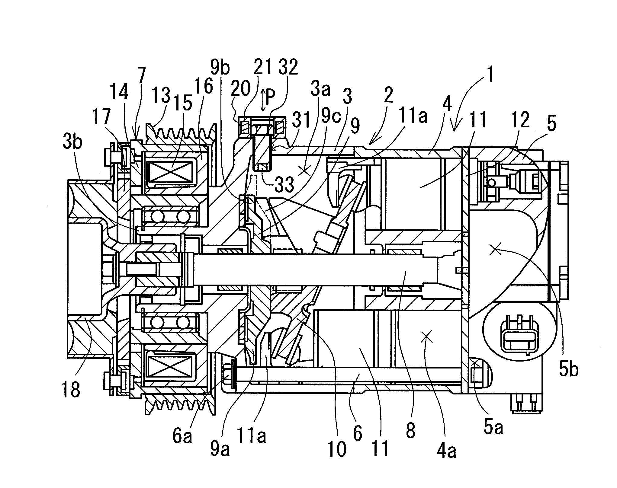
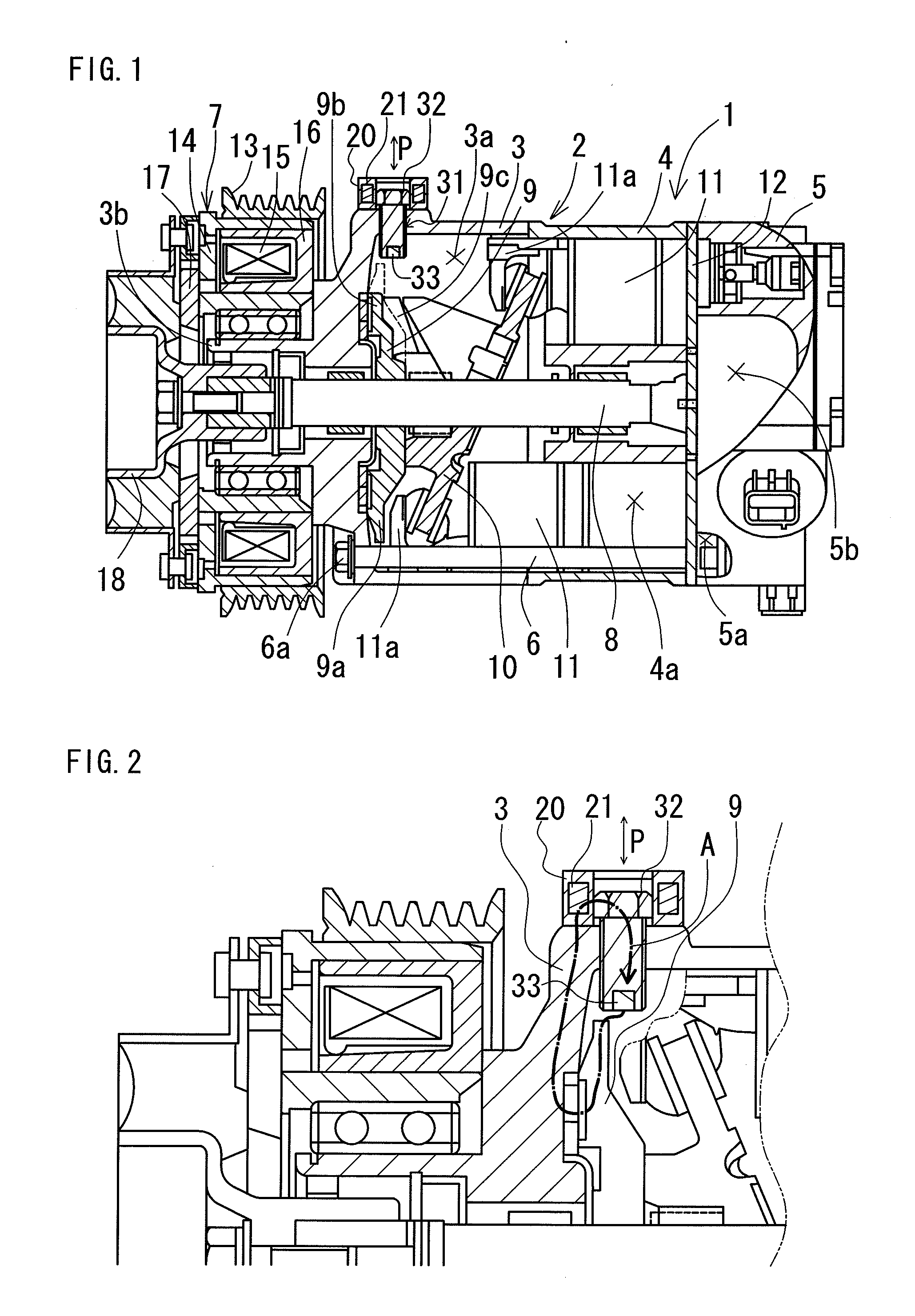
[0077]Below, the present invention will be concretely explained by an embodiment with reference to the figures.

first embodiment

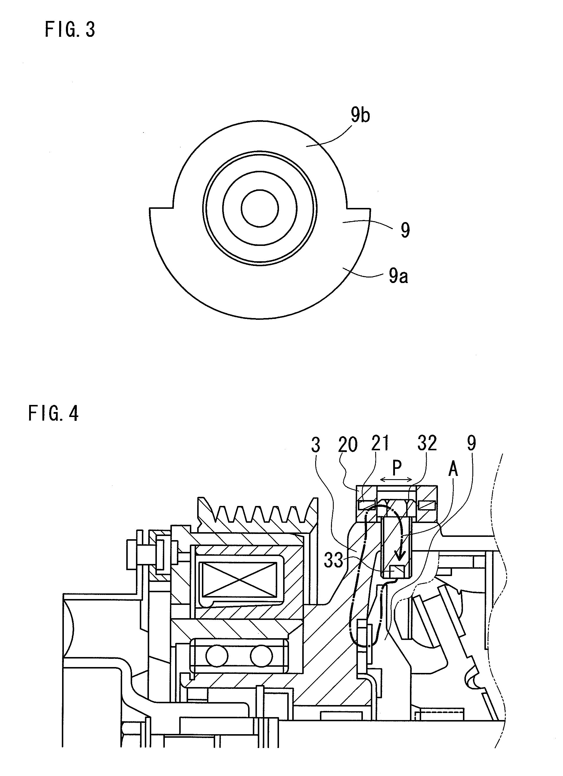
[0078]Note that in this first embodiment, the compressor according to the present invention is illustrated by a variable displacement compressor for a vehicle air conditioner that is provided with a detecting device on the head portion of a drain bolt and in which the compression capacity changes depending on the change of the tilt of the skew plate, which will be described below.

1. Structure of the Compressor

[0079]As shown in FIG. 1, a compressor 1 according to the present embodiment has a body 2 that includes a tubular aluminum (non-magnetic body) front housing 3, a cylinder block 4, and a rear housing 5 (provided as an example of the “housing member” according to the present invention). While the back end of the front housing 3 abuts the front end of this cylinder block 4 and the front end of the rear housing 5 abuts the back end of the cylinder block 4 via a valve plate 12, the threaded portions (not illustrated) of a plurality of bolt members 6 made of a ferrous metal (magnetic...

second embodiment

[0090]In a second embodiment, the compressor according to the present invention is exemplified by a variable displacement compressor for a vehicle air conditioner that is provided with a magnetic member that covers the head portion of the drain bolt and in which the compression capacity changes depending on the change of the tilt of the skew plate, which will be described below.

[0091]As shown in FIG. 5 and FIG. 6, the compressor 1 according to the second embodiment is provided with a structure that is similar to the first embodiment, and differs in being provided with the yoke member 34, which is a magnetic member according to the present invention. This yoke member 34 is provided on the head portion of the drain bolt 32 along with the magnetic sensor 20, and is provided with a shape that is in contact with the portion of the head portion of the drain bolt 32 that is not covered by the magnetic sensor 20. In addition, the yoke member 34 is made of a ferrous metal, which is a magneti...


PUM


Abstract

This compressor includes housing members that form a body; a drive shaft linked to a drive power source via an electromagnetic clutch; movable members moving in cooperation with the drive shaft and carrying out the compression of a fluid; a detected body moving in cooperation with the drive shaft; a drain bolt screwed into a drain bolt hole provided in a housing member in proximity to the detected body; and a detecting device detecting the rotation state of the drive shaft by the detected body. The drain bolt is provided with a permanent magnet, the detecting device is structured by a magnetic sensor that includes a magnetic impedance element, and the magnetic sensor is provided at the head portion of the drain bolt. Thereby, it is possible to provide a rotation detecting mechanism by using an existing drain bolt, without requiring the machining of a hole in the compressor body.

Description

BACKGROUND OF THE INVENTION[0001]1. Field of the Invention[0002]The present invention relates to compressors for vehicle air conditioners, and in particular, relates to a compressor that can be provided with a rotation detecting mechanism that does not require the machining of a hole in the compressor body only in order to provide the rotation detecting mechanism, and that is compact and inexpensively manufactured.[0003]2. Description of the Related Art[0004]Conventionally, compressors for vehicle air conditioners are known that are provided with a rotation detecting mechanism in order to detect rotation malfunctions due to seizing and the like. For example, as shown in FIG. 19, in this rotation detecting mechanism, a through hole 102 is formed in a non-magnetic housing member 101, and a detecting sensor 104 is mounted in this through hole 102 via an O-ring 103. In addition, the change in the magnetic flux that flows from the magnet 106 to the core 107 accompanying the rotation of a...

Claims


Application Information

Patent Timeline
Patent Type & Authority Applications(United States)
IPC IPC(8): F04B49/00
CPCF04B27/10F04B27/1036F04B27/1054F04B2201/1206F04B49/06F04B49/103F04B27/1081
Inventor ONO, MAKOTOSAKUMA, WATARU
Owner TOYOTA BOSHOKU KK
Why Eureka
Try Eureka