Radio propagation estimating method and radio propagation estimating apparatus

a radio propagation and estimating method technology, applied in the field of radio propagation estimating programs, can solve the problems of low calculation accuracy and low calculation accuracy, and achieve the effect of reducing path calculation load and high calculation accuracy

Active Publication Date: 2008-07-03
HITACHI LTD
View PDF5 Cites 36 Cited by
  • Summary
  • Abstract
  • Description
  • Claims
  • Application Information

AI Technical Summary

Benefits of technology

[0029]According to the invention of this application, the ray launching method is used to narrow down the object surfaces in the target space and the imaging method is used to estimate a path using the object surfaces that have been narrowed down, thereby ensuring high calculation accuracy while reducing the path calculation load.
[0030]According to the another invention of this application, the probabilistic

Problems solved by technology

However, though the technology disclosed in JP-A-10-62468 certainly reduces the calculation load, the paths leading to the receiving point cannot sometimes be found because the calculation is performed only for the object surfaces viewable from both the transmitting point and the receiving point, resulting in

Method used


Image

  • Radio propagation estimating method and radio propagation estimating apparatus
  • Radio propagation estimating method and radio propagation estimating apparatus
  • Radio propagation estimating method and radio propagation estimating apparatus

Examples


first embodiment

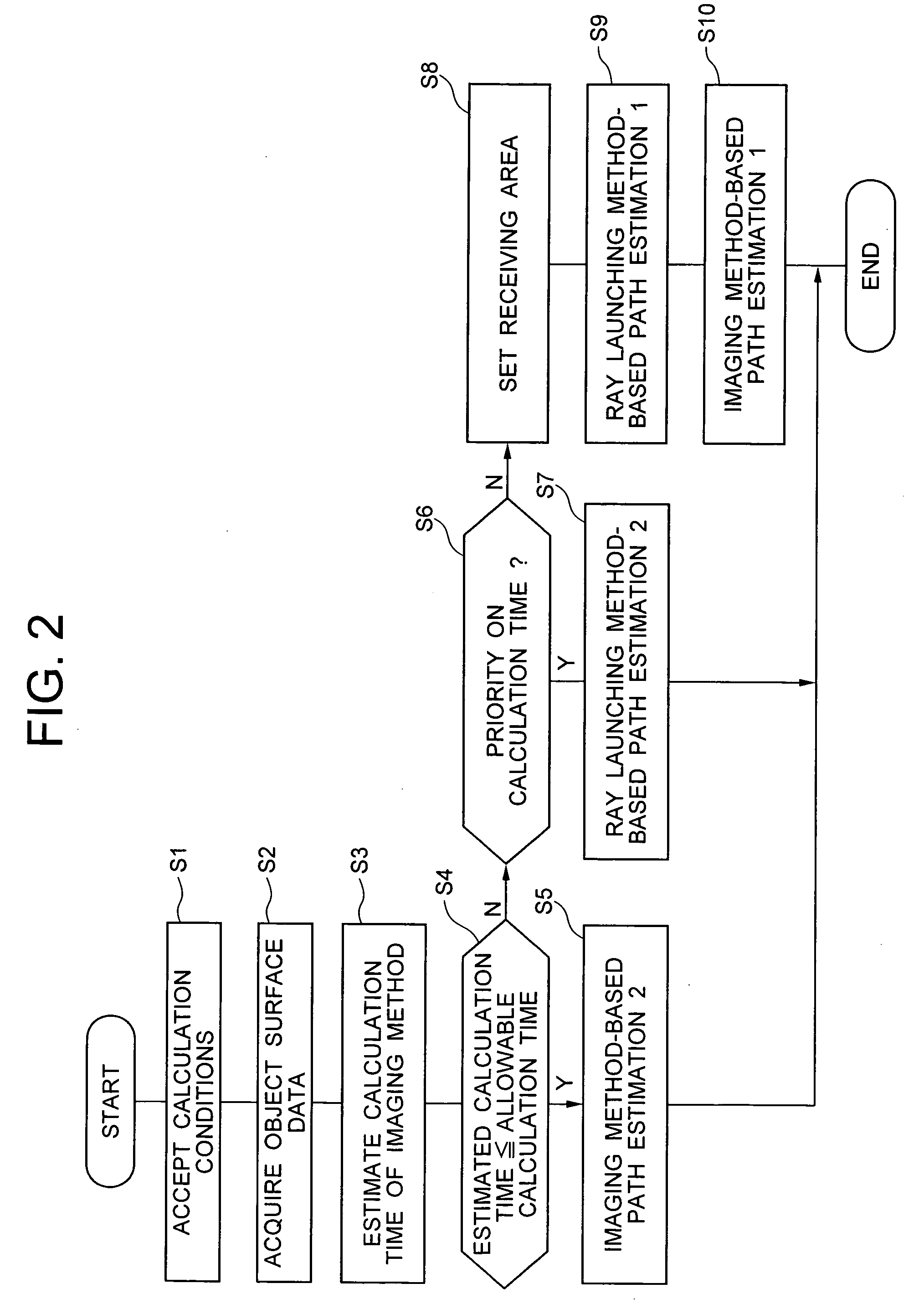
[0048]First, a radio propagation estimating apparatus in a first embodiment of the present invention will be described with reference to FIGS. 1-9.

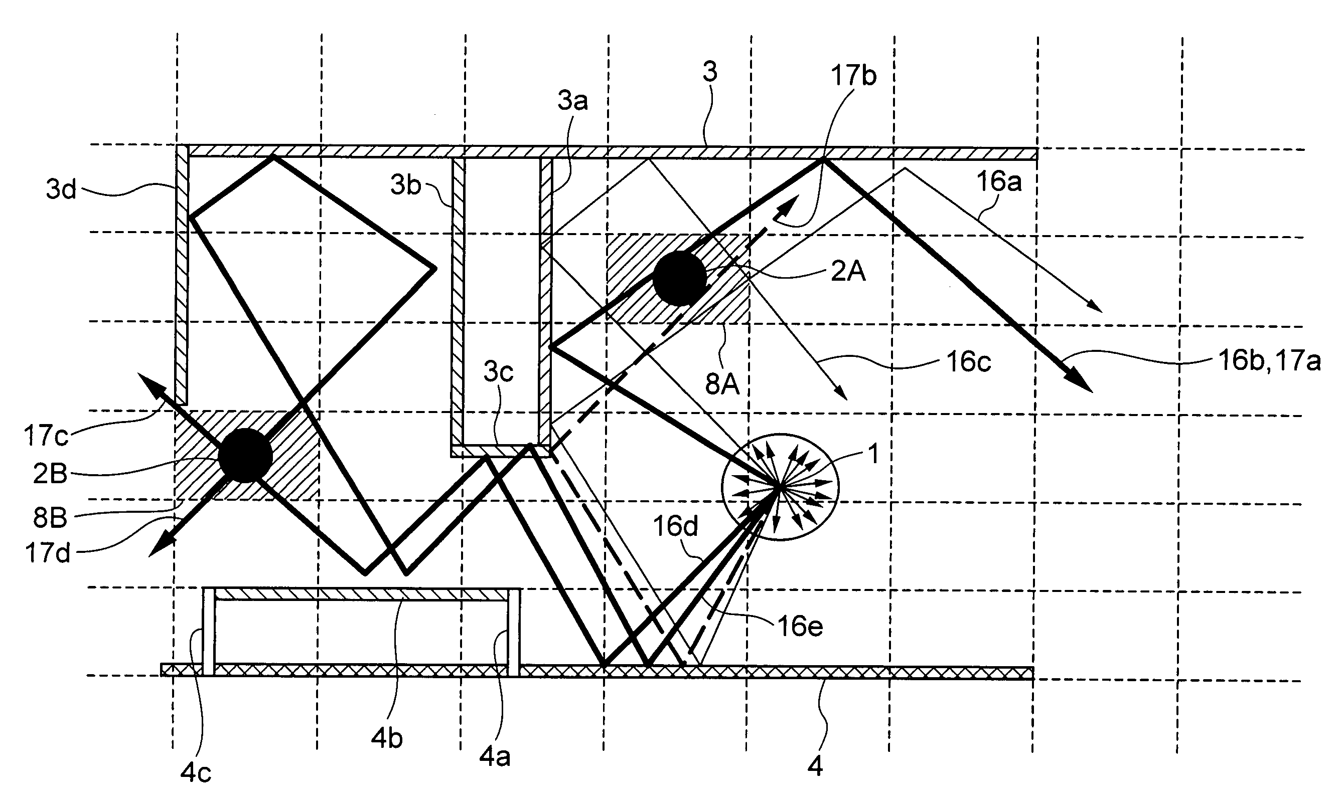
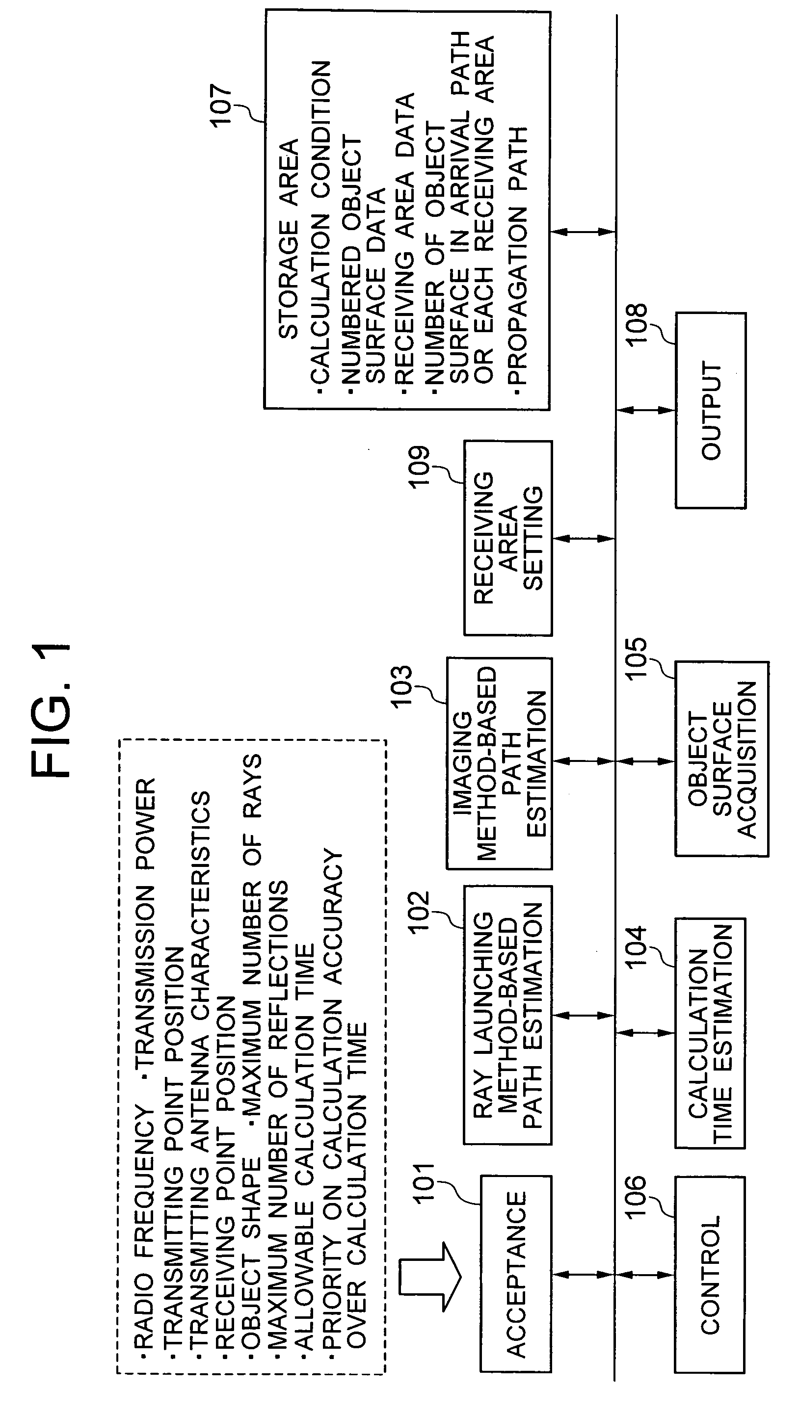
[0049]As shown in FIG. 1, the radio propagation estimating apparatus in this embodiment functionally comprises an acceptance unit 101 that accepts calculation conditions necessary for estimating a radio propagation path, a ray launching method-based path estimation unit 102 that estimates a radio propagation path using the ray launching method, an imaging method-based path estimation unit that estimates a radio propagation path using the imaging method, a calculation time estimation unit 104 that estimates a time for calculating a radio propagation path using the imaging method, an object surface acquisition unit 105 that acquires object surface (flat surface) data, which represents the surface of an object, from the shape and the position of the object such as a structure or a natural object accepted by the acceptance unit 101, a receivi...

second embodiment

[0089]Next, a radio propagation estimating apparatus in a second embodiment of the present invention will be described with reference to FIG. 10-FIG. 12.

[0090]As shown in FIG. 10, the radio propagation estimating apparatus in this embodiment has the configuration of the radio propagation estimating apparatus in the first embodiment and further comprises a space division unit 112 that divides a target space using a predetermined method, an arriving power estimation unit 110 that estimates the arriving power supplied to a predetermined position in the divided areas generated by the space division unit 112, and a transmission power pseudo conversion unit 111 that pseudo-converts the transmission power at a transmitting point. Like the control unit 106 described above in the first embodiment, those components 110, 111, and 112 each comprise a memory and a CPU that executes programs stored in this memory.

[0091]Next, the following describes the operation of the radio propagation estimatin...


PUM


Abstract

A radio propagation path from a transmitting point to a receiving point is estimated accurately with a relatively small amount of calculation. A predetermined-size receiving area including the receiving point is set, radio propagation paths from the transmitting point to the receiving area is estimated by a ray launching method, object surfaces existing in the paths are extracted, and a radio propagation path from the transmitting point to the receiving point is estimated by an imaging method using only the extracted object surfaces.

Description

BACKGROUND OF THE INVENTION[0001]The present invention relates to a radio propagation estimating program, a radio propagation estimating method, and an apparatus executing this method that are used in the layout design of a base station in a wireless LAN system, a mobile phone / PHS system, and a broadcasting system for analyzing a radio propagation path in a predetermined space, and more particularly to a radio propagation estimating program, a radio propagation estimating method, and an apparatus executing this method for analyzing the power of a radio wave that arrives at a receiving point.[0002]Recently, a wireless network system such as a mobile phone, a PHS, a wireless LAN, and a DSRC (Dedicated Short Range Communication) finds many applications as more and more infrastructure facilities are built and the costs of apparatuses are lowered. In such a wireless network system, the radio propagation characteristics greatly affect the data communication performance due to factors such...

Claims


Application Information

Patent Timeline
IPC IPC(8): H04Q7/20H04W16/22
CPCH04B17/327H04W16/225
Inventor SATO, YOSHIHITOOKURA, YOSHINORI
Owner HITACHI LTD
Why Eureka
Try Eureka