
Devices and methods for ablating near AV groove

a technology of ablating devices and av grooves, applied in the field of epicardial ablation devices, can solve problems such as addition of arrythimia, and achieve the effect of avoiding ablation

Inactive Publication Date: 2008-07-03
ST JUDE MEDICAL ATRIAL FIBRILLATION DIV
View PDF74 Cites 19 Cited by
  • Summary
  • Abstract
  • Description
  • Claims
  • Application Information

AI Technical Summary

Benefits of technology

[0009]In yet another embodiment, a first electrode can be separated from a second electrode along a first axis of the device, and a third electrode element is spaced from the first and second electrodes along a second, orthogonal axis. The first, second, and third electrodes convey signals measured along the different axes between different pairs of the electrodes and the electrodes can continuously record multiple electrical events at different relative orientations at one location. The multiple electrodes on different axes essentially form an array of sensors to detect atrial and ventricular electrical impulses, for example, so that the user can determine which if any part of the array is contacting atrial tissue and which if any part of the array is contacting ventricular tissue. This information coupled with the positioning of the sensors on the array locates the ablating surfaces or distal end of the device with respect to the heart's electrophysiological features, similar to mapping techniques. For example, an array spanning the AV groove will detect atrial impulses at one end and ventricular impulses on another, and these impulses can be easily differentiated by techniques known in the art. Typically, these sensor electrodes are bipolar electrodes, but combinations with unipolar electrodes can also be used. Additionally or alternatively, one or more ring electrodes spaced away from sensor electrode(s) can be used. Also, as noted, pacing electrodes can be used. The recorded signals include the characteristic atrial and ventricular signals and other, smaller AV node bypass signals typically associated with the AV groove or other anatomical feature. In another example, the changes in measurements while moving the ablating surface of the ablation catheter on the epicardial surface of the heart allow the location to be ascertained with respect to the AV node, ganglionated plexi, or other anatomical or electrophysiological active areas of the heart. In this way, for example, the physician can avoid any ablation near or in the AV groove.

Problems solved by technology

Ablating the AV groove may cause additional arrythimias such as ventricular tachycardia.

Method used


Image

  • Devices and methods for ablating near AV groove
  • Devices and methods for ablating near AV groove
  • Devices and methods for ablating near AV groove

Examples


Embodiment Construction

[0019]As used herein, the words “preferred,”“preferentially,” and “preferably” refer to embodiments of the invention that afford certain benefits, under certain circumstances. However, other embodiments may also be preferred, under the same or other circumstances. Furthermore, the recitation of one or more preferred embodiments does not imply that other embodiments are not useful and is not intended to exclude other embodiments from the scope of the invention and no disclaimer of other embodiments should be inferred from the discussion of a preferred embodiment or a figure showing a preferred embodiment.

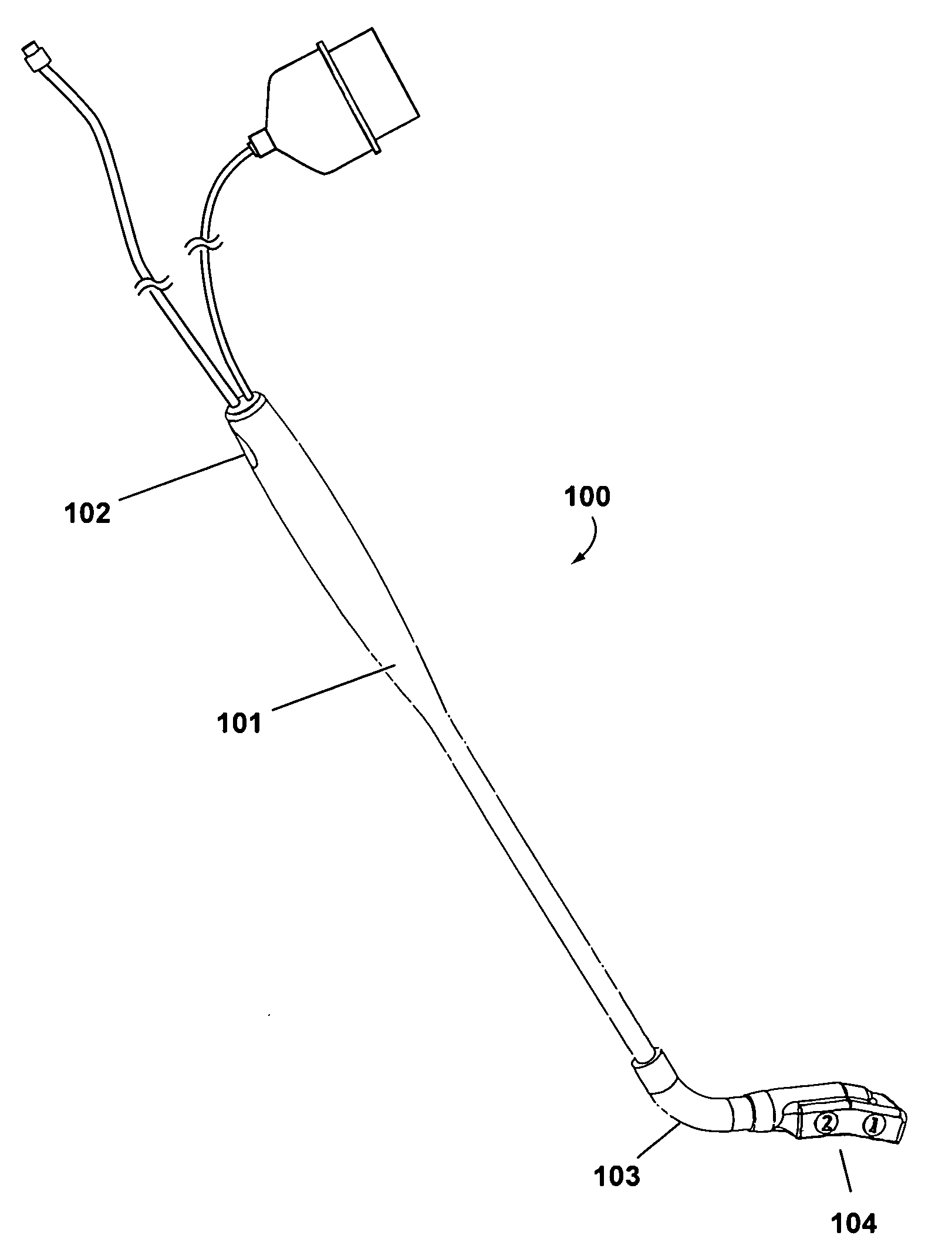
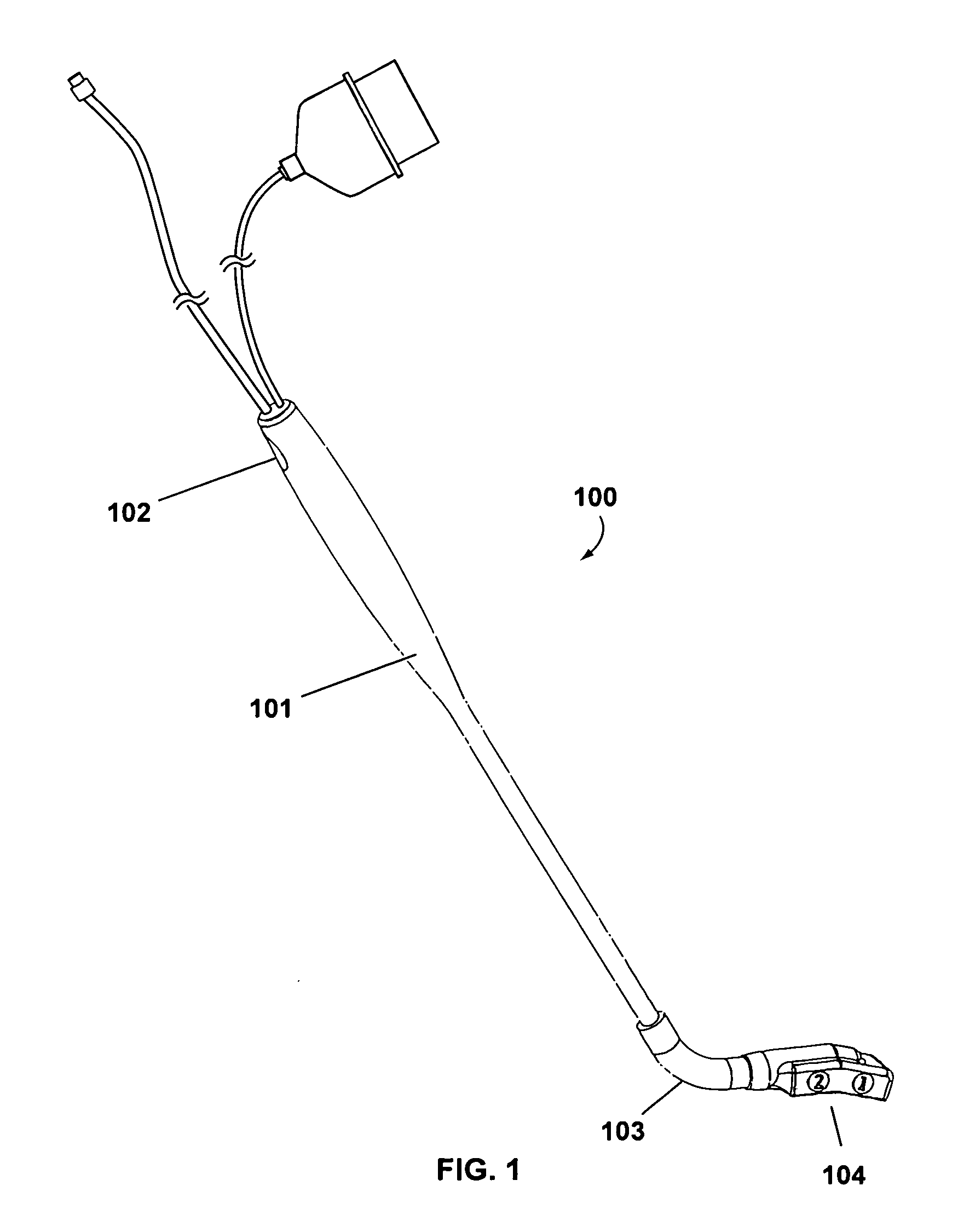
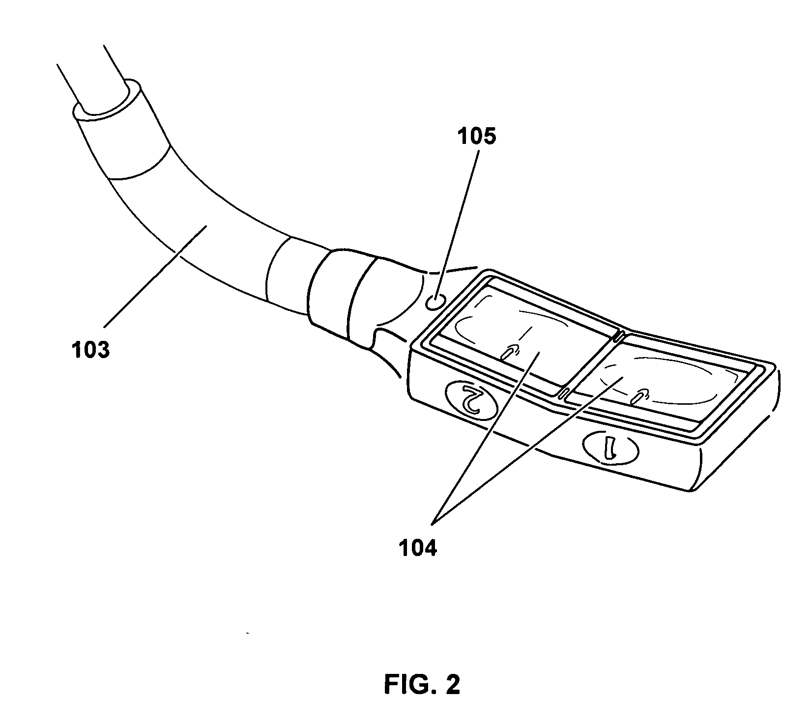
[0020]Referring to FIGS. 1 and 2, an ablation device according to one embodiment of the present invention is shown. Device 100 includes an elongated, rigid shaft 101 having a proximal end 102 and a flexible distal end 103. In particularly preferred embodiments, the device 100 has at least one ablation element, and preferably two ablation elements 106. The ablation device may, of cour...


PUM


Abstract

The invention encompasses a device, system and methods for ablating tissue, where a ablating device includes an elongated shaft having a flexible distal end, and at least one ablation element and at least one electrode detecting electrical signals of the heart, such that a user can assess whether the at least one ablation element is located on a tissue of the atrioventricular (AV) groove of a patient's heart.

Description

BACKGROUND OF THE INVENTION[0001]a. Field of the Invention[0002]The instant invention generally relates to devices and methods for treating electrophysiological diseases of the heart. In particular, the instant invention relates to devices and methods for epicardial ablation for the treatment of atrial fibrillation.[0003]b. Background Art[0004]It is well known that atrial fibrillation results from disorganized electrical activity in the heart muscle (the myocardium). Procedures for treating atrial fibrillation may involve the creation of a series of elongated transmural lesions—that is, lesions extending through a sufficient thickness of the myocardium to block electrical conduction—to create conductive corridors of viable tissue bounded by scar tissue. Such procedures may be performed from outside the heart (epicardial ablation) using devices introduced into the patient's chest. Various techniques may be used for the creation of epicardial transmural lesions, including, for example...

Claims


Application Information

Patent Timeline
Patent Type & Authority Applications(United States)
IPC IPC(8): A61B5/0402A61N7/00
CPCA61B17/2202A61B17/2251A61B18/1482A61N2007/0078A61N1/3625A61N7/022A61B2017/00243
Inventor PODMORE, JONATHAN L.VASKA, MATTHIAS
Owner ST JUDE MEDICAL ATRIAL FIBRILLATION DIV
Learn More