

Tube punching and collaring system, device and method
- Summary
- Abstract
- Description
- Claims
- Application Information
AI Technical Summary
Benefits of technology
Problems solved by technology
Method used
Image

Examples
Embodiment Construction
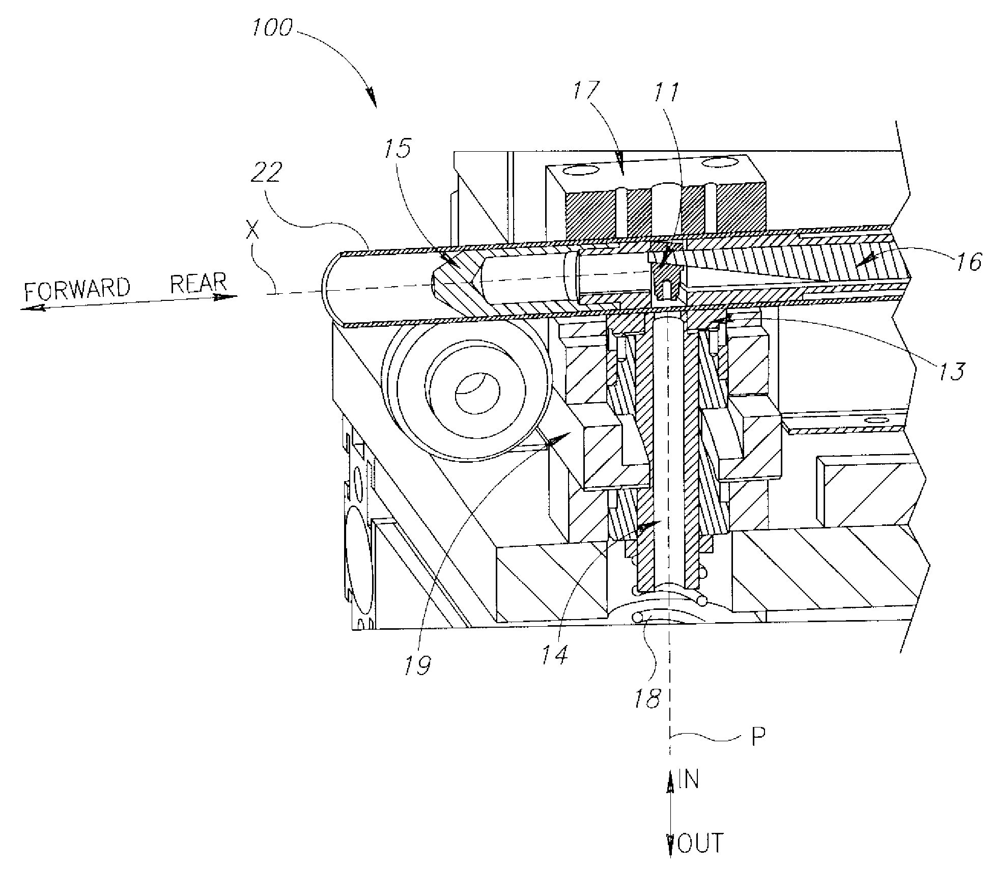
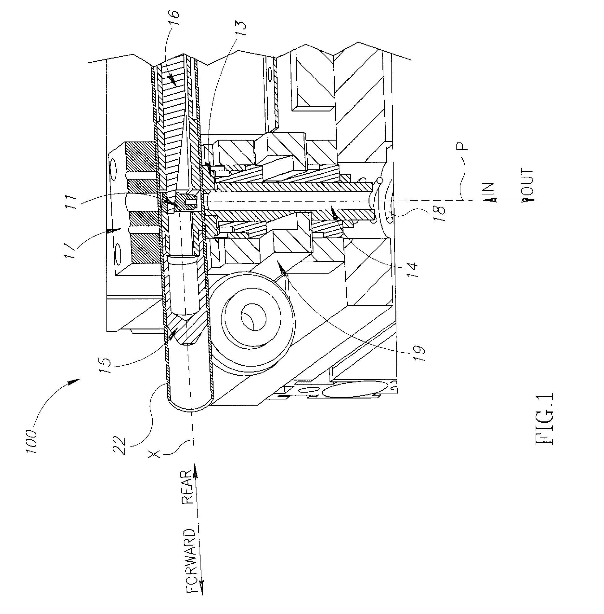
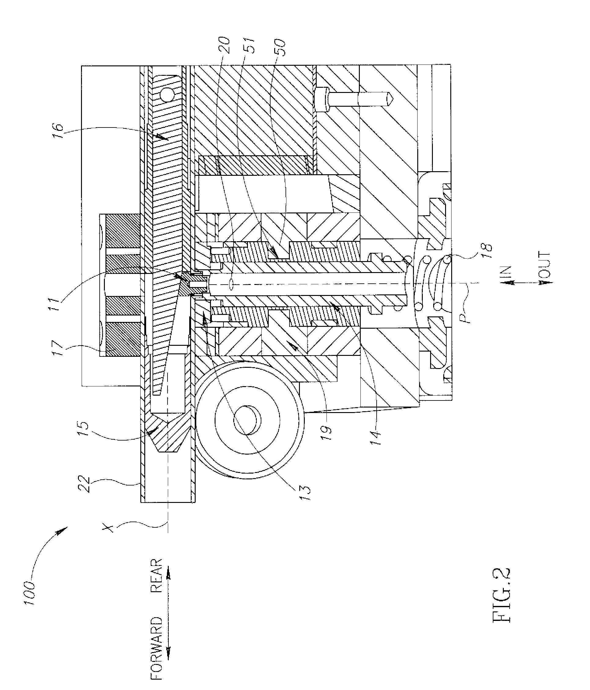
[0012]The present invention relates to a machine that combines a highly efficient punching method with a system and / or device that provides quality collar.
[0013]Generally speaking, a collar is examined by the similarity to a cylindrical shape, i.e., the similar a collar to a cylinder, the better is the quality of the collar, since a substantially cylindrical collar facilitates brazing of tubes on said collar.
[0014]It is to be understood that the term “punching a hole into a tube” or grammatical variations thereof, refer to a method wherein the direction of the punching is from the inner side of the tube to the outer side of the tube.
[0015]According to an embodiment of the invention, the present invention provides a method for punching at least one hole in a tube comprising the steps of: providing a system comprising a punch and a mold, placing the tube on the system such that the tube extends along a system axis, the punch is located within the tube and the mold is located outside o...
PUM
| Property | Measurement | Unit |
|---|---|---|
| Radius | aaaaa | aaaaa |
| Radius | aaaaa | aaaaa |
| Radius | aaaaa | aaaaa |
Abstract
Description
Claims
Application Information