
Contra-tapered tank design for cross-counterflow radiator

a technology of counterflow radiator and cross-counterflow, which is applied in the direction of indirect heat exchangers, lighting and heating apparatus, stationary conduit assemblies, etc., can solve the problems of additional hardware such as elbows, hoses, clamps and fittings, labor, and associated costs, and achieves reduced potential leakage points, less weight, and lateral compactness.

Inactive Publication Date: 2008-07-10
DELPHI TECH INC
View PDF14 Cites 20 Cited by
  • Summary
  • Abstract
  • Description
  • Claims
  • Application Information

AI Technical Summary

Benefits of technology

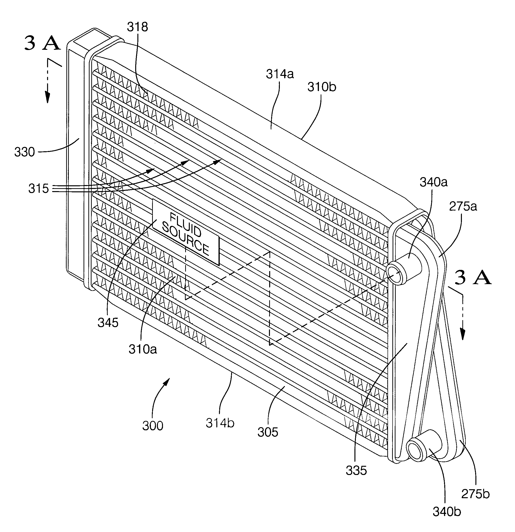
[0016]An advantage of the present invention is that the inlet and outlet port openings extend in the same general direction toward the fluid source. This preferred orientation of the inlet / outlet ports eliminates the need for additional plumbing hardware such as elbows, hoses, clamps, and fittings to redirect the heat exchange fluid flow toward the fluid source, thereby resulting in less weight and reduced potential leak points.
[0017]A further advantage of contra-tapering the chambers of the inlet / out tank toward the central core opposing surfaces is that this provides a compact inlet / outlet tank design resulting in a laterally compact heat exchanger. A compact inlet / outlet tank design also allows for lesser coolant usage resulting in additional weight savings.
[0018]A still further advantage is that the contra tapered chambers provide improved flow distribution and pressure drop for the heat exchange fluid as it flows through the central core. This allows for even more compact heat exchanger design due to greater increase efficiency of the heat exchanger.

Problems solved by technology

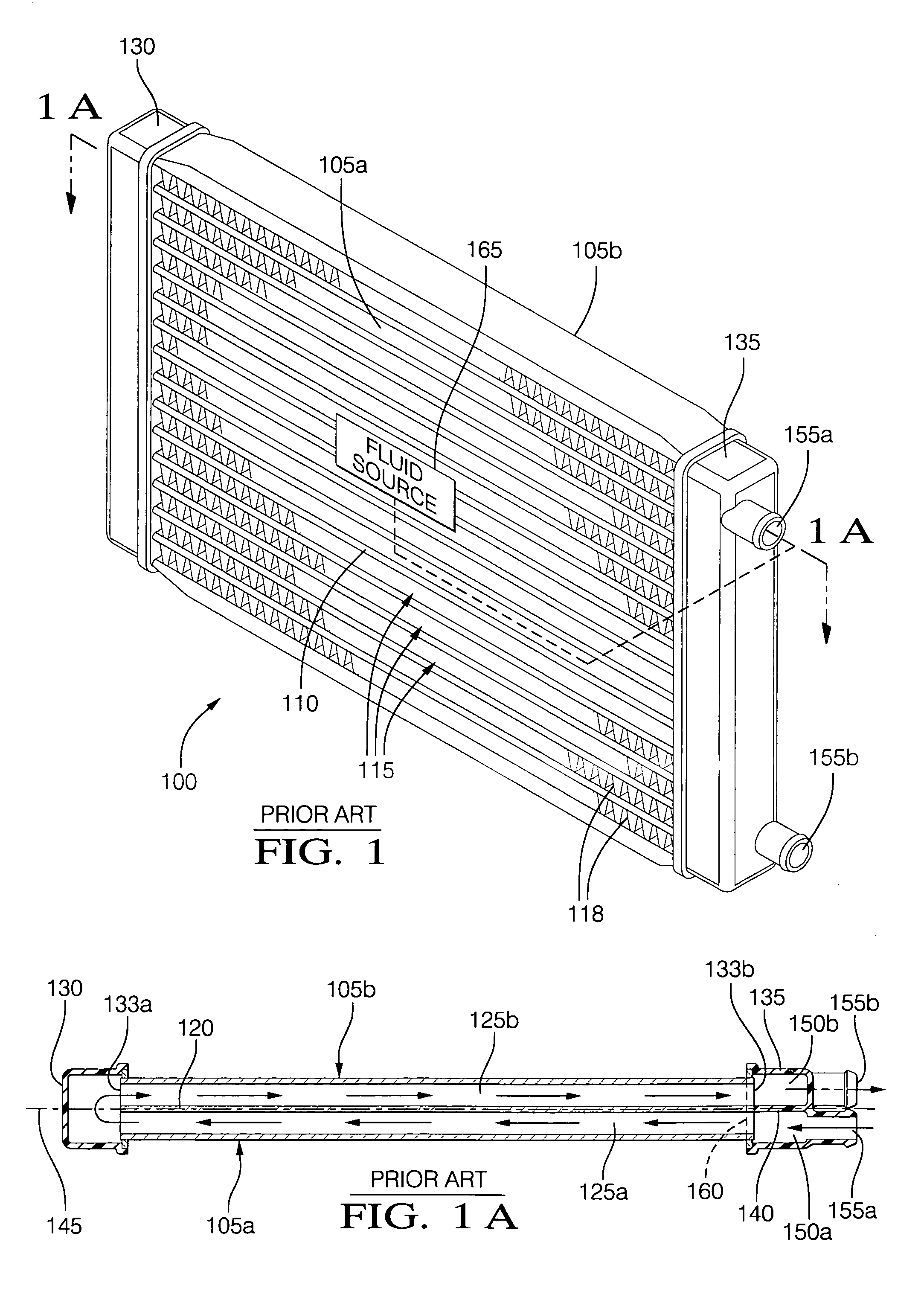
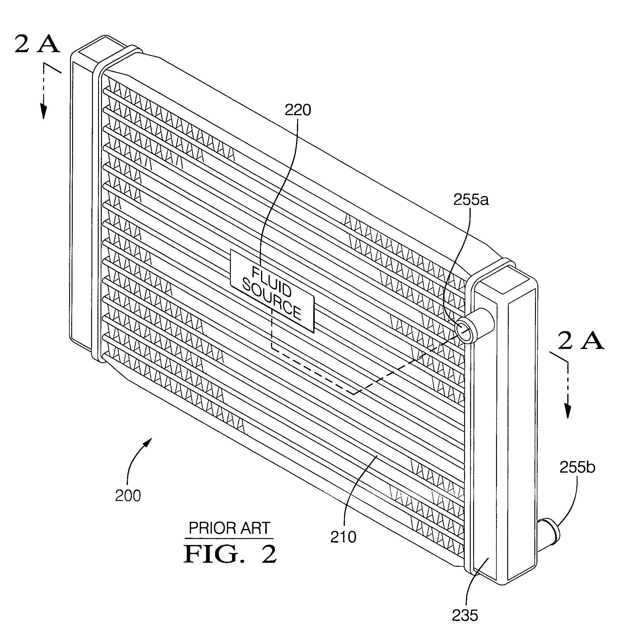
A disadvantage of the prior art inlet / outlet tanks 135, 235 is that additional hardware such as elbows, hoses, clamps, and fittings are required to orient either the inlet ports 155a, 255a or outlet ports 155b, 255b toward the fluid source 165, 220.
This results in additional space utilization, weight, plumbing hardware, potential leak points, labor, and associated cost.

Method used


Image

  • Contra-tapered tank design for cross-counterflow radiator
  • Contra-tapered tank design for cross-counterflow radiator
  • Contra-tapered tank design for cross-counterflow radiator

Examples


Embodiment Construction

[0029]Shown in FIGS. 3 through 6, in accordance with a preferred embodiment of this invention, is a cross-counter flow heat exchanger such as a cross-counter flow radiator utilized to cool an internal combustion engine of an automobile.

[0030]FIG. 3 is a perspective view of cross-counterflow heat exchanger 300 having a central core 305 with opposing faces 310a, 310b, one facing toward, and one away from hot fluid source 345. Fluid source 345, in this case, would be an internal combustion engine of a motor vehicle (not shown). Both of the opposed faces 310a, 310b are situated substantially perpendicular to hot fluid source 345. Central core 305 has a plurality of substantially parallel liquid flow tubes 315 for conveyance of heat exchange fluid. Fins 318 are inter-disposed between flow tubes 315 for improved heat dissipation and increased structural integrity. Outer flow tubes 315 of central core 305 are bounded by first support member 314a and a second support member 314b. First and ...


PUM


Abstract

The invention relates to a cross-counterflow heat exchanger, such as a cross-counterflow radiator for a motor vehicle, having an improved inlet / outlet tank wherein the inlet and outlet chambers are laterally off-set allowing the inlet and outlet ports to be oriented in the same general direction toward the fluid source; more particularly, the inlet and outlet chambers are tapered thereby providing improved flow distribution and pressure drop for fluid flow; still more particularly, the return tank inlet and outlet chambers are contra-tapered allowing the inlet and outlet ports to be substantially aligned resulting in a laterally compact heat exchanger.

Description

TECHNICAL FIELD OF INVENTION[0001]The invention relates to a cross-counterflow heat exchanger, such as a cross-counterflow radiator for a motor vehicle, having an improved inlet / outlet tank wherein the inlet and outlet chambers are contra-tapered, thereby allowing the inlet and outlet ports to extend in the same general direction toward a fluid source.BACKGROUND OF INVENTION[0002]Cross-counter flow heat exchangers, such as a cross-counter flow radiator, are used to convey heat away from hot powertrain components such as the engine, transmission, compressor, or even a fuel cell of an automobile. With the advent of new powertrain cooling challenges, the need for mass reduction, and the decreasing available space within the engine compartment of an automobile, cross-counter flow radiators are becoming more desirable because of its higher cooling capacity per unit volume.[0003]A cross-counter flow radiator is part of a closed loop system wherein the radiator is hydraulically connected t...

Claims


Application Information

Patent Timeline
Patent Type & Authority Applications(United States)
IPC IPC(8): F28D7/06
CPCF28D1/05375F28F9/0263F28F9/0214
Inventor PAPAPANU, STEVEN JAMES
Owner DELPHI TECH INC
Learn More