Information Reproducing Apparatus, Information Reproducing Method, Information Reproducing Program, and Information Recording Medium
a technology information, which is applied in the field of information reproducing apparatus, information reproducing method, information reproducing program, information recording medium, can solve the problems of inability to accurately reproduce the process and slow response to a change in the rotation speed of the spindle motor, so as to prevent the occurrence of erroneous detection
- Summary
- Abstract
- Description
- Claims
- Application Information
AI Technical Summary
Benefits of technology
Problems solved by technology
Method used
Image


Examples
first embodiment
(II) First Embodiment
[0067]A first embodiment according to the present invention based on the principle will be described with reference to FIGS. 3 to 7.
[0068]The FIG. 3 is a block diagram showing a schematic configuration of an information reproducing apparatus according to the first embodiment, FIGS. 4 to 6 are block diagrams each showing the detailed configuration of the information reproducing apparatus, and FIG. 7 is a flowchart showing the operation of the information reproducing apparatus.
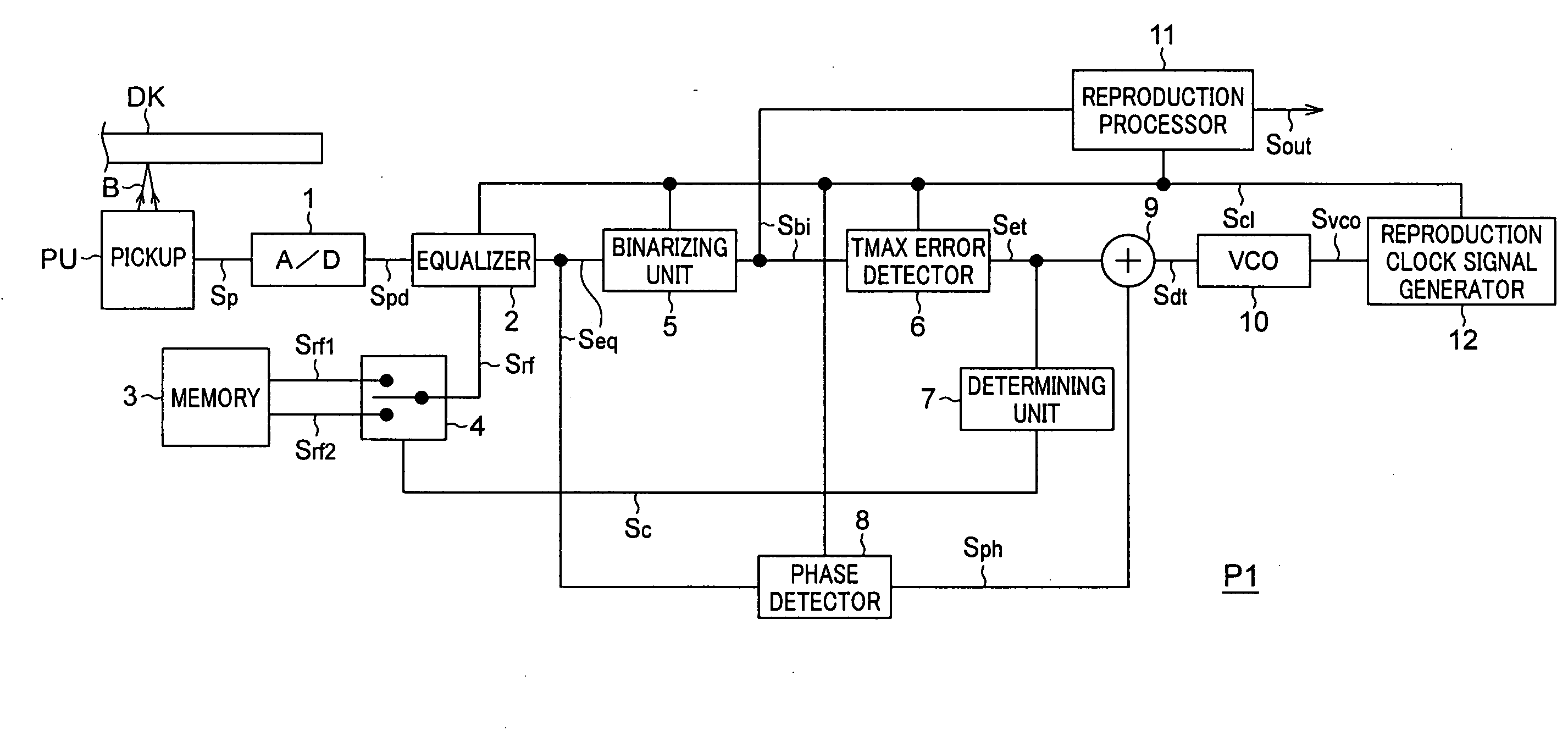
[0069]As shown in FIG. 1, an information reproducing apparatus P1 according to the first embodiment has a pickup PU, an A / D (Analog / Digital) converter 1, an equalizer 2 of the invention, a memory 3, a switch 4, a determining unit 7 as control means, a binarizing unit 5, a TMAX error detector 6 as detecting means, a phase detector 8, an adder 9, a VCO (Voltage Controlled Oscillator) 10, a reproduction processor 11, and a reproduction clock signal generator 12.
[0070]As shown in FIG. 4, the TMA...
second embodiment
(III) Second Embodiment
[0113]A second embodiment as another embodiment according to the invention will now be described with reference to FIGS. 8 and 9.
[0114]FIG. 8 is a block diagram showing a schematic configuration of an information reproducing apparatus of the second embodiment. FIG. 9 is a diagram showing a detailed configuration of the information reproducing apparatus (equalizer 2B).
[0115]In the first embodiment, by switching the frequency characteristic of one equalizer 2 when the difference between the frequency of the detection signal Sp and the frequency of the reproduction clock signal Scl is large, erroneous detection of a TMAX error is prevented. The second embodiment described below relates to the case where an equalizer for detecting a TMAX error and an equalizer for reproducing AV information and the like are separately provided.
[0116]In FIGS. 8 and 9, similar reference numerals are designated to components similar to those of the information reproducing apparatus P...
third embodiment
(IV) Third Embodiment
[0130]A third embodiment as further another embodiment according to the invention will now be described with reference to FIG. 10. FIG. 10 is a block diagram showing a schematic configuration of an information reproducing apparatus according to the third embodiment.
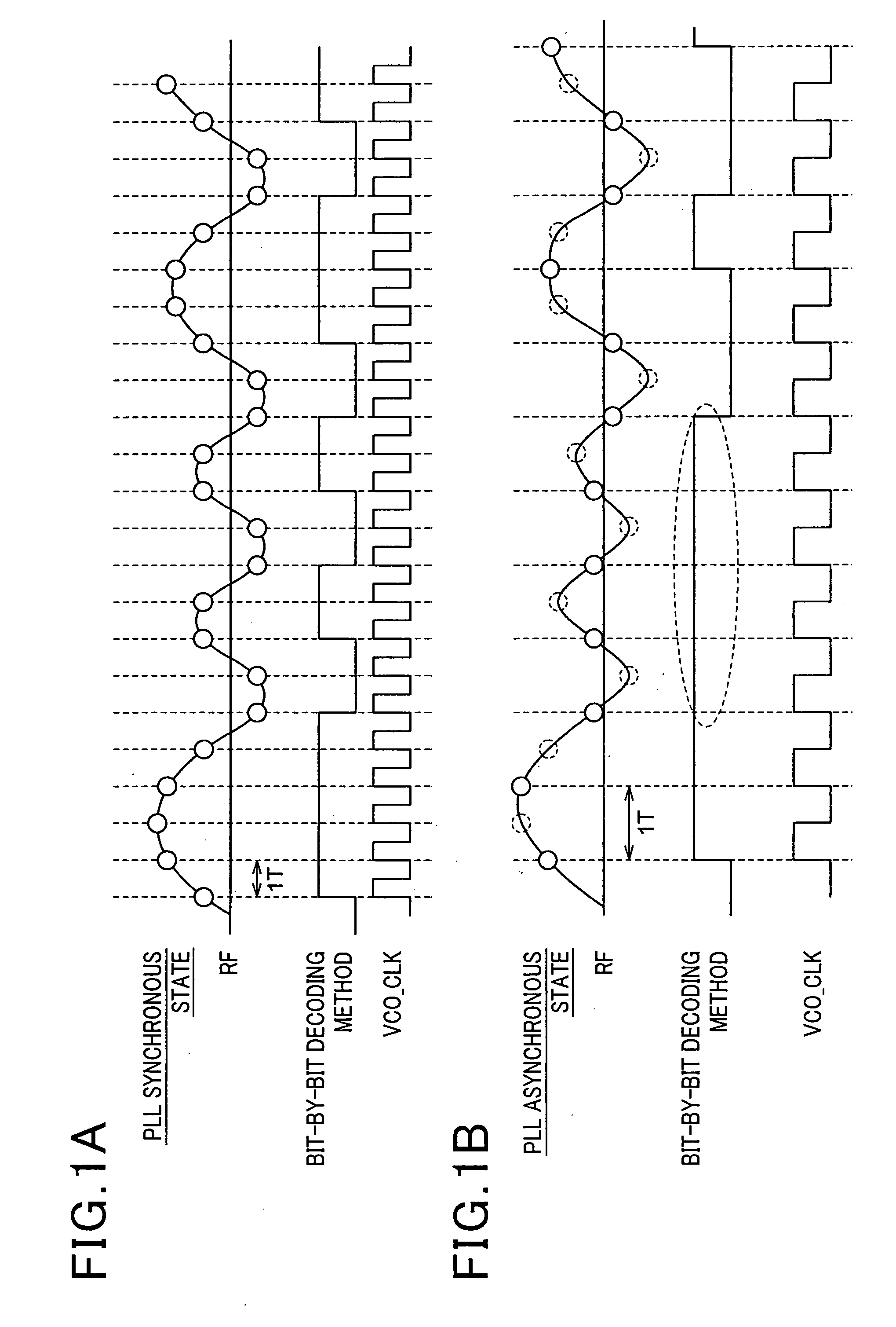
[0131]In the first embodiment, erroneous detection of a TMAX error is prevented by switching the frequency characteristic of one equalizer 2 when the difference between the frequency of the detection signal Sp and the frequency of the reproduction clock signal Scl is large, and the binarizing unit 5 is commonly used for decoding AV information and for detecting a TMAX error. The third embodiment described below relates to the case where the Viterbi decoding method is used for the binarizing process for decoding, and the bit-by-bit decoding method is used for the binarizing process for detecting a TMAX error.
[0132]In FIG. 10, similar reference numerals are designated to components similar to those of t...
PUM
| Property | Measurement | Unit |
|---|---|---|
| frequency | aaaaa | aaaaa |
| threshold frequency | aaaaa | aaaaa |
| time | aaaaa | aaaaa |
Abstract
Description
Claims
Application Information
 - R&D Engineer
- R&D Manager
- IP Professional
- Industry Leading Data Capabilities
- Powerful AI technology
- Patent DNA Extraction
Browse by: Latest US Patents, China's latest patents, Technical Efficacy Thesaurus, Application Domain, Technology Topic.
© 2024 PatSnap. All rights reserved.Legal|Privacy policy|Modern Slavery Act Transparency Statement|Sitemap